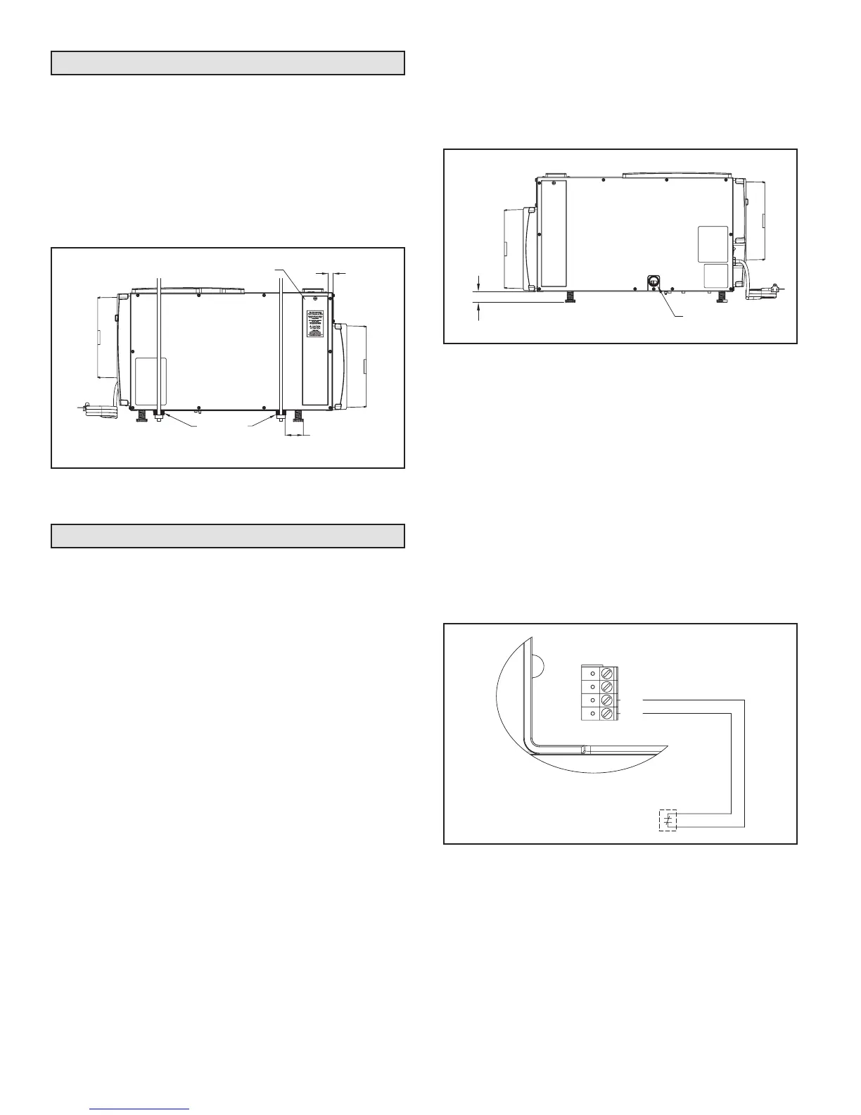
LEVELING
The feet can be adjusted to level the unit, and if required,
to accommodate drain ttings and a secondary condensate
pan. Leveling is required to ensure proper drainage from
the dehumidier. See Figure 9.
Drain Installation
The drain outlet on the dehumidier can be hard piped
using a 3/4" PVC Slip x 3/4" MNPT tting and 3/4" nominal
drain tubing or the provided 3/4" MNPT x 3/4" hose barb
tting and 3/4" clear PVC tubing can be used to drain
the dehumidier. Always maintain a constant downward
slope from the dehumidier to the drain and do not allow
soft tubing to curl up which may result in air lock. NOTE:
PTFE thread seal tape is recommended for the threaded
connection and hand tighten only. If hard pipe is used,
PVC primer and cement is recommended for the slip t
connection.
CONDENSATE PAN, CONDENSATE PUMP
AND FLOAT SWITCH
Always install the dehumidier in a condensate pan when
locating in or above a nished space. Adhere to local codes
regarding draining of the condensate pan. If a condensate
pump is needed, install it in the condensate pan as well.
Install a condensate overow safety switch (i.e. oat switch)
in the condensate pan, remove the factory installed jumper
wire between the Float Switch terminals on the control and
wire the oat switch to the dehumidier as shown in Figure
10. Overow safety switches on condensate pumps can
be wired to the Float Switch terminals in a similar fashion.
Figure 9. Level the Unit
Figure 10. Float Switch Wiring
0.38" MIN
2.00" MAX
3/4" FNPT DRAIN
FLOAT
Switch
DH DH
NORMALLY CLOSED
FLOAT SWITCH
90-1885
90-1857
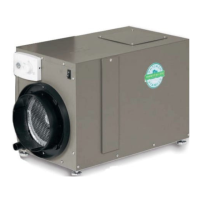
Suspended Installation
If hanging the unit, use 1/4" (minimum) threaded rod and
two unistruts to support the base, just inside the leveling
feet. It is recommended that vibration isolators be placed
between the unistruts and dehumidier base. See Figure
8. Do not position threaded rods over lter access doors.
Allow 3" between the unit and threaded rods on the service
access to remove the side panel if service is required. There
must be a minimum clearance of 12" on one side of the
unit to allow for removal of the lter.
Figure 8. Suspended Installation
FILTER ACCESS DOOR
5/8"
INLET
OUTLET
VIBRATION
ISOLATORS
2-1/8" CLEARANCE
FOR LEVELING FEET
90-1951
6