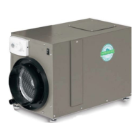
NORTH, EAST
OR WEST SIDE
OF HOME
OUTDOOR
TEMPERATURE
SENSOR
SENSOR
SENSOR
BRACKET
ABOVE EXPECTED
SNOW LINE
OUTDOOR
TEMPERATURE SENSOR
LEADS
36" MAX.
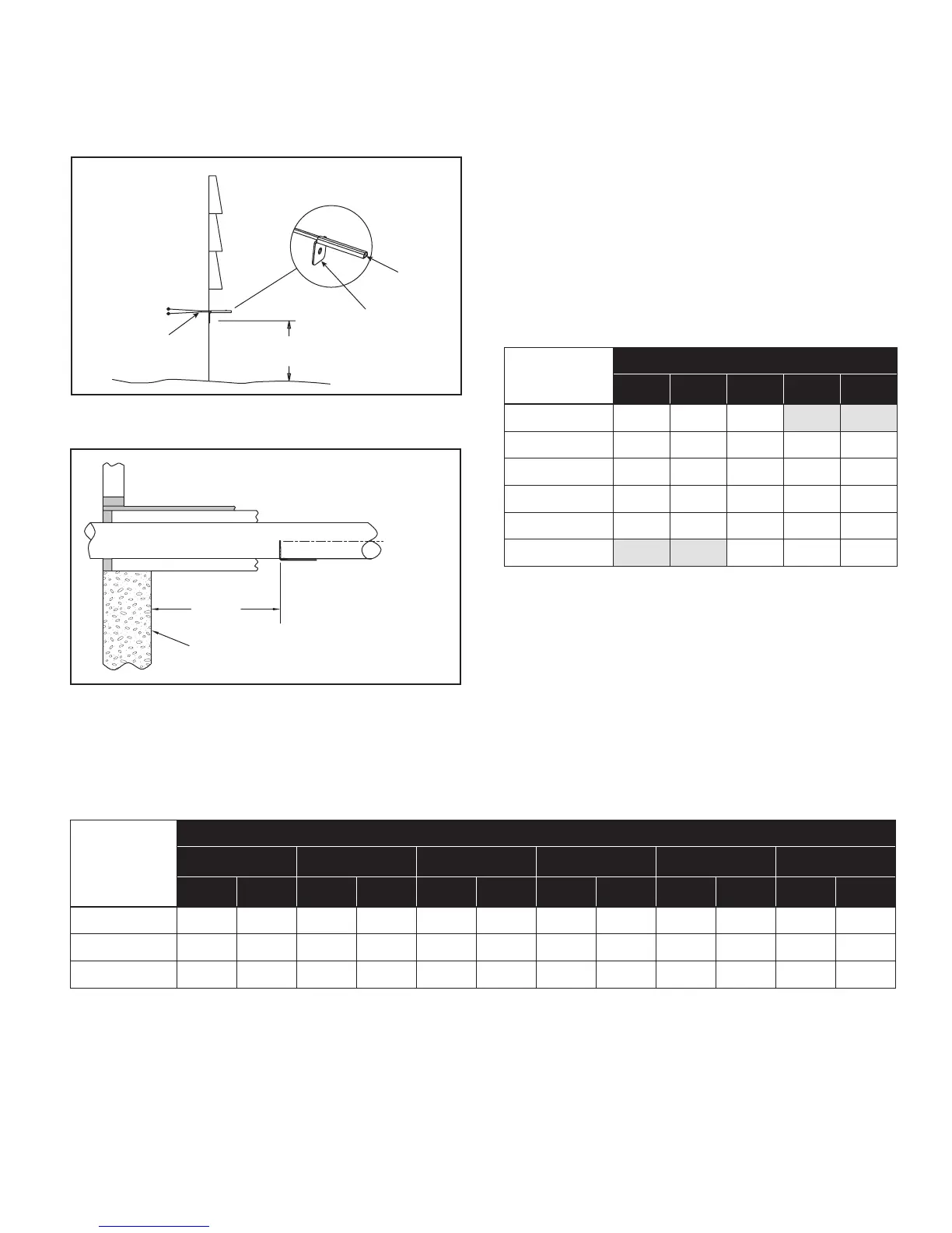
CENTER LINE
OUTSIDE WALL
B2202617-D
B2202617-E
OUTDOOR TEMPERATURE SENSOR INSTALLATION
The 58N66 Outdoor Temperature Sensor should be installed
outside in a shaded location, or in the outdoor air intake
duct.
DETERMINE VENTILATION REQUIREMENTS
Calculating Airow Requirement
1. The MINIMUM ventilation requirement is calculated
using ASHRAE 62.2-2010.
ASHRAE Airow in CFM = [House Area in Sq. Ft. x 0.01] +
[(Number of Bedrooms +1) x 7.5]
NOTE: Use ‘Number of Bedrooms + 1’ or ‘Number of
Occupants’, whichever is larger.
2. Table 1 shows the calculated airflow values to the
nearest 5 CFM.
3. Record the required CFM. ________
Table 1. CFM Required
House Sq. Ft.
Number of Bedrooms
2 3 4 5 6
1000 35 40 50
1500 40 45 55 60 70
2000 45 50 60 65 75
2500 50 55 65 70 80
3000 55 60 70 75 85
3500 75 80 90
Determine Fresh Air Delivery Rate
1. Measure the negative static pressure of the return system
at the location where the fresh air intake duct enters the
return duct or dehumidier inlet.
2. See Table 2 for estimated inlet airow in CFM, based
on duct type, length and available negative pressure.
Use an airow measuring device for a more accurate
airow delivery rate.
3. Record the delivered CFM. ________
Figure 27. ODT Mounted Outside
Figure 28. ODT Mounted in Intake Duct
Table 2. CFM Delivered
Duct Length
Negative Static Pressure ("w.c.) as Measured for Return Duct or Plenum
0.05 0.1 0.15 0.2 0.25 0.3
Flex Pipe Flex Pipe Flex Pipe Flex Pipe Flex Pipe Flex Pipe
10 ft. 60 65 85 90 105 110 120 125 135 140 150 160
20 ft. 55 60 80 85 100 105 115 120 130 135 140 150
30 ft. 50 55 75 80 95 100 110 115 125 130 130 140
NOTE: For the table above, 6" ex duct is laid loose with two, wide 90° bends and a fully opened damper. Rigid pipe values
are based on 6" duct, two 90° elbows, and a fully open damper. In both cases, the air intake is through a metal vent hood
with inlet screen. Airow may need to be adjusted up or down for variations in duct system.
17