I R222)
marked I.iii on
)jn.
201, R202,
R222, R223,
.rd.
and Pin Ci) of
G) and Pin©
•Cammeter
uit
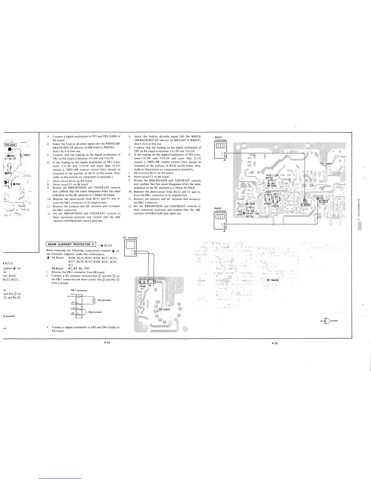
3. Connect a digital multimeter to TP2 and TP4 (GND) of
PA board.
4. Select the built-in all-white signal (Set the WHITE/OP-
ERATE/SET UP selector on HB board to WHITE).
Don't do it in free run.
5. Confirm that the reading on the digital multimeter of
TP2 on PA board is-between +3 LOY and +33.5Y.
6. If the reading on the digital multimeter of TP2 is bet-
ween +31.0Y and +33.5Y and more than 32.5V,
mount a JMQl/4W resistor (metal-film) should be
mounted at the portion of R222 on PA board. (Nor-
mally in this portion no component is mounted.)
7. Short-circuit R231 on PA board.
8. Short-circuit Cl on BI board.
9. Rotate the BRIGHTNESS and CONTRAST controls
and confirm that the raster disappears when the value
indicated on the DC ammeter is 2.20mA ±0.35mA.
I 0. Remove the short-circuit from R23 i and Cl and re-
store the PB-I connector to its original state.
11. Remove the jumpers and DC ammeter and reconnect
the PB-I connector.
12. Set the BRIGHTNESS and CONTRAST controls to
their maximum positions and confirm that the ABL
operates (OVERLOAD Lamp Lights up).
BEAM CURRENT PROTECTOR 2
( B R239)
When replacing the following components (marked
~
on
the schematic diagram), make this confirmation.
~
PA Board .. D204, D216, R203, R204, R231, R232,
R237, R238, R239, R240, R241, R247,
IC3
PB Board .. R3, R4, R6, FBT
I. Remove the PB-I connector from PB board.
2. Connect a DC ammeter between Pin (D and Pin Ci) of
the PB-I connector and short-circuit Pin G) and Pin ©
with a jumper .
PB-1 connector
IHVIII
FBT---H-<J.++---~
DC ammeter
3. Connect a digital multimeter to TP3 and TP4 (GND) of
PA board.
4-14
4. Select the built-in all-white signal (Set the WHITE/
OPERATE/SET UP selector on HB board to WHITE).
Don't do it in free run.
5. Confirm that the reading on the digital multimeter of
TP3 on PA board is between +31.0Y and +33.5Y.
6. If the reading on the digiatal multimeter of TP3 is bet-
ween +3 l.0Y and +33.5Y and more than 32.5V,
mount a JMQ1/4W resistor (metal-film) should be
mounted at the portion of R239 on PA board. (Nor-
mally in this portion no component is mounted.)
7. Short-circuit R213 on PA board.
8. Short-circuit CI on BI board.
9. Rotate the BRIGHTNESS and CONTRAST controls
and confirm that the raster disappears when the value
indicated on the DC ammeter is 2.20mA ±0.35mA.
10. Remove the short-circuit from R213 and Cl and re-
store the PB-I connector to its original state.
11. Remove the jumpers and DC ammeter and reconnect
the PB-I connector.
12. Set the BRIGHTNESS and CONTRAST controls to
their maximum positions and confirm that the ABL
operates (OVERLOAD lamp lights up).
DC ammeter
8-
«iJ
¾;I
digital
multimeter
l~J
digital
multimeter
I ~J----------------
4-15
CT £)jumper,
Ul
f-
z
w
~
f-
Ul
:J
-,
0
<(