(J)
f-
z
w
::;
f-
(J)
:::J
-,
0
<
.;
HIGH VOLTAGE HOLD DOWN ADJUSTMENT
AND CONFIRMATION
( B R227, R228)
When replacing the following components (marked IA on
the schematic diagram), make this adjustment.
IA DCT block
PA Board .. D205, D207, D215, IC2, R201, R202,
R213, R214, R225, R226, R227, R228,
R243, R245
It is necessary to use an electrostatic voltmeter or equiva-
lent for this adjustment. Connect the electrostatic voltmeter
to the anode cap.
Even though an electrostatic voltmeter may not be used,
connect digital multimeter to([). pin of IC4 on PA Board.
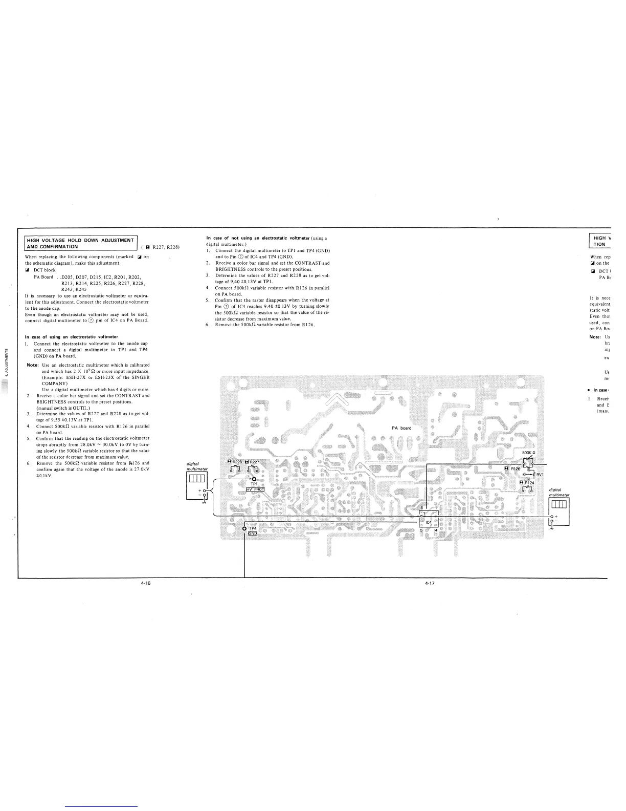
In case of using an electrostatic voltmeter
I. Connect the electrostatic voltmeter to the anode cap
and connect a digital multimeter to TPI and TP4
(GND) on PA board.
Note: Use an electrostatic multimeter which is calibrated
and which has 2 X 10
9
[l or more input impedance.
(Example: ESH-27X or ESH-23X of the SINGER
COMPANY)
Use a digital multimeter which has 4 digits or more.
2. Receive a color bar signal and set the CONTRAST and
BRIGHTNESS controls to the preset positions.
(manual switch is OUTll.)
3. Determine the values of R227 and R228 as to get vol-
tage of 9.55 ±0.13V at TPI.
4. Connect 500krl variable resistor with RI 26 in parallel
on PA board.
5. Confirm that the reading on the electrostatic voltmeter
drops abruptly from 28.0kV - 30.0kV to 0V by turn-
ing slowly the S00krl variable resistor so that the value
of the resistor decrease from maximum value.
6. Remove the 500krl variable resistor from RI 26 and
confirm again that the voltage of the anode is 27.0kV
±O.lkV.
4-16
In case of not using an electrostatic voltmeter (using a
digital multimeter.)
I. Connect the digital multimeter to TPI and TP4 (GND)
and to Pin([) of IC4 and TP4 (GND).
2. Receive a color bar signal and set the CONTRAST and
BRIGHTNESS controls to the preset positions.
3. Determine the values of R227 and R228 as to get vol-
tage of 9 .40 ±0. I 3V at TP I.
4. Connect 500krl variable resistor with RI 26 in parallel
on PA board.
5. Confirm that the raster disappears when the voltage at
Pin ([) of IC4 reaches 9.40 ±0.13V by turning slowly
the 500krl variable resistor so that the value of the re-
sistor decrease from maximum value.
6. Remove the S00krl variable resistor from RI 26.
digital
multimeter
l~J
4-17
HIGH V
TION
When rep
IA on the
I.iii DCTI
PA B<
It is nece
equivalent
static volt
Even tho1
used, con
on PA Bo;
Note: Us
br;
inJ
ex
Us
m<
• In case,
I. Recei•
and E
(mam