·ostatic voltmeter (using a
eter to TPI and TP4 (GND)
'4 (GND).
rnd set the CONTRAST and
he preset positions.
!27 and R228 as to get vol-
sistor with R 126 in parallel
appears when the voltage at
) ±Q .13 V by turning slow Jy
· so that the value of the re-
um value.
~
resistor from R 126.
4-17
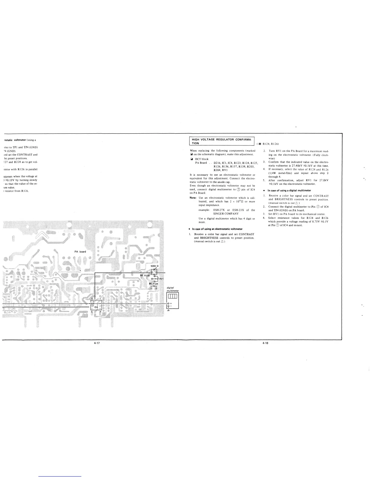
HIGH VOLTAGE REGULATOR CONFIRMA-
TION
(
~
RI 24, RI 26)
When replacing the following components ( marked
l.i on the schematic diagram), make this adjustment.
l.i DCT block
PA Board .. D216, ICl, IC4, R123, Rl24, R125,
R126, R136, R137, R138, R203,
R204, RV!
It is necessary to use an electrostatic voltmeter or
equivalent for this adjustment. Connect the electro-
static voltmeter to the anode cap.
Even though an electrostatic voltmeter may not be
used, connect digital multimerter to 0) pin of IC4
on PA Board.
Note: Use an electrostatic voltmeter which is cali-
brated, and which has 2 x 10
9
S1 or more
input impedance.
example: ESH-2 7X or ESH-23 X of the
SINGER COMPANY
Use a digital multimeter which has 4 digit or
more.
• In case of using an electrostatic voltmeter
1. Receive a color bar signal and set CONTRAST
and BRIGHTNESS controls to preset position.
(manual switch is out Il)
2. Turn RV! on the PA Board for a maximum read-
ing on the electrostatic voltmeter. ( Fully clock-
wise)
3. Confirm that the indicated value on the electro-
static voltmeter is 27.40kV ±0.lkV at this time.
4. If necessary, select the value of RI 24 and RI 26
(1/4W metal-film) and repeat above step 2
through 4.
5. After confirmation, adjust RV 1 for 27 .0kV
±0.1 kV on the electrostatic voltmeter.
• In case of using a digital multimeter
I. Receive a color bar signal and set CONTRAST
and BRIGHTNESS controls to preset position.
(manual switch is out Jl)
2. Connect the digital multimeter to Pin CD of 1C4
and TP4 (GND) on PA board.
3. Set RV 1 on PA board to its mechanical center.
4. Select resistance values for Rl24 and Rl26
which provide a voltage reading of 8.75V ±0.lV
at Pin CD of IC4 and mount.
4-18