22 (E)
Chapter 1 Overview
Location and Function of Parts
1 PARALLEL REMOTE1/2 connectors
(1: female, D-sub 9-pin, 2: modular connector)
Form a parallel switch and controls the monitor
externally. The pin assignment and factory setting
function assigned to each pin are given below.
1: D-sub 9-pin
15
96
2: modular connector
1 6
All pin function assignments can be changed with the
REMOTE menu.
For information about the REMOTE menu, see “ [D]
Assigning the Remote Control Functions — REMOTE
Menu” on page 37(E).
Pin number
1
Set input signal channel 1 (numeric keypad
function)
2
Set input signal channel 2 (numeric keypad
function)
3 Set red tally lamp on or off
4 Set green tally lamp on or off
5 Select sync signal (SYNC button function)
6 Set underscan on or off
7 Set a 16:9 aspect ratio on or off
8
Functions
Set the 4:3 area marker display on or off
9
GND
Pin number
1
Set input signal channel 1 (numeric keypad
function)
2
Set input signal channel 2 (numeric keypad
function)
3 Set red tally lamp on or off
4 Set green tally lamp on or off
5 GND
6 Set underscan on or off
Functions
Cable with D-sub 9-pin plugs
(not supplied)
Monitor 1 Monitor 2
IN
SERIAL
REMOTE
SERIAL
REMOTE
OUT
IN
OUT
To switch each function between on and off or
between enable and disable, change pin connections in
the following way.
ON or enabled: Short each pin and pin 9 together for
D-sub 9-pin.
Short each pin and pin 5 together for modular
connector.
OFF or disabled: Leave each pin open.
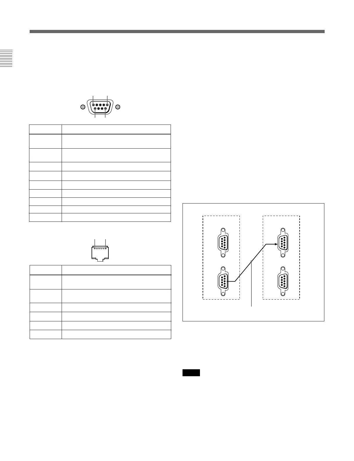
2 SERIAL REMOTE connectors
(female, D-sub 9-pin)
These are RS-485 serial interface connectors, used for
connecting two or more BVM-xxE/F/G, BVM-Dxx
and HDM-xxE series monitors.
The IN and OUT connectors form a loop-through
connection.
Connect two monitors using a cable with D-sub 9-pin
plugs such as an RCC-5G (not supplied) as shown in
the figure.
3 Input option slots (three slots)
The monitor may be fitted with optional input adaptors
up to three.
The BKM-129X is installed to the monitor at the
factory.
Notes
•The BKM-142HD uses two input option slots.
•Each adaptor can also be installed into SLOT 1.
Install any adaptor to SLOT 1.