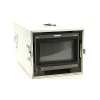
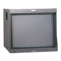
Do you have a question about the Sony BVM-D32E1WA and is the answer not in the manual?
Manual intended for qualified personnel; warnings about shock, fire, and injury.
Identifies critical safety components marked with '!' for replacement.
Warnings about exposure to rain, moisture, and opening the cabinet.
FCC, ICES-003, CE marking, EMC, and Low Voltage Directive compliance.
Recommendations for safe installation in racks regarding temperature, airflow, and loading.
Safety measures for operation, cleaning, and repacking the unit.
Precautions for rack installation, magnetic fields, and CRT safety.
Highlights multiformat support, high-resolution CRT, separate control unit, and auto functions.
Details the main power switch, AC input socket, and fuse.
Explains the function of menu operation buttons like MENU, UP/DOWN, ENTER.
Describes the functions of the menu operation buttons on the control unit.
Explains how to access and navigate through the monitor's menu system.
Illustrates the multi-level menu structure and the functions of each main menu item.
Explains color temperature adjustment and recommended preceding steps.
Describes knob adjustment (MANUAL) and automatic adjustment using a probe (PROBE).
Details manual adjustment of gain and bias using control knobs.
Guides for automatic adjustment using SONY BKM-14L probe.
Explains setting input signal data for each channel with the INPUT CONFIGURATION menu.
Details format selection for COMPOSITE, YC, COMPONENT, and SDI signals.
Details pin assignments for parallel remote control and function settings.
Covers settings for channel entry, power-up conditions, and degauss delay.
Introduces the ALIGNMENT menu for geometry and convergence adjustments.
Explains adjustments for beam landing shift and CRT color unevenness.
Describes manual adjustment and automatic adjustment using BKM-14L probe.
Details manual adjustment of beam landing shift direction and fine adjustment.
Guides for automatic beam landing adjustment using the BKM-14L probe.
Lists required tools and specifications for CRT replacement adjustments.
Details pre-adjustment settings for ROTATION, LCC, and digital uniformity.
Provides detailed steps for adjusting focus using the F1 and F2 buttons.
Procedure for adjusting H. BLK LEFT, RIGHT, CENTER, and PHASE.
Procedure for adjusting H. BLK LEFT, RIGHT, CENTER, and PHASE for 480/60p signals.
Procedure for adjusting H. BLK LEFT, RIGHT, CENTER, and PHASE for 1080/48i signals.
Step-by-step guide for adjusting H. SIZE, H. LIN BAL, H. LIN, H. KEY BAL, H. KEY.
Describes HMC and VMC correction using the 6-pole magnet.
Procedure for aligning red and green dots horizontally with 4-pole and 6-pole magnets.
Procedure for aligning red and green dots vertically with 4-pole and 6-pole magnets.
Details adjusting G2 REF for pedestal DC voltage at the cathode.
Outlines adjustments for landing, digital uniformity, and color temperature.
Procedure for obtaining parameters for converting RGB drive voltage to chromaticity.
Checks and adjustments for +B (135V) voltage when parts are replaced.
Procedure for checking and adjusting the high voltage regulator circuit.
Checks and adjusts the high voltage hold-down circuit.
Checks the beam current protector circuit for proper operation.
Describes checking protector operation when R, G, B buttons are activated.
Details current specifications and procedures for testing overload protection.
Lists adjustments required for maintenance and parts replacement of the BK board.
Procedure to adjust bright center by setting BRIGHT data and connecting oscilloscope.
Procedure to equalize pedestal and clamp offset pulse for R-Y and B-Y signals.
Procedure to adjust pulse level for PB and PR signals by checking output waveform.
Procedure to adjust R-Y and B-Y gain by checking GREEN waveform.
Procedure to equalize black level and setup signal levels for Y, G, and B signals.
Procedure to equalize 100 IRE level and pulse level for R, G, and B signals.
Procedure to adjust bias reference pulse by checking TP306 output.
Procedure to adjust drive reference pulse by checking TP306 output.
Procedure to equalize black level of TP105, TP305, and TP505 outputs.
Procedure to equalize 100 IRE levels of TP105, TP305, and TP505 outputs.
Procedure to adjust frequency characteristics of R, G, and B output waveforms.
Describes video output amplifier, G2 control, and overload detection.
Describes the switching regulator system for high voltage generation.
Explains the circuit protecting CRT from abnormal anode voltage.
Details the circuit protecting CRT from excessive anode current.
Overview of BC board's control functions: CPU, communication, signal generation, OSD.
Describes H. delay circuit and AFC circuit for sync and deflection signal processing.
Explains horizontal deflection circuit and linearity correction.
Provides a high-level block diagram of the system's main functional blocks.
Continues the system block diagram, showing power supply and control interfaces.
Illustrates the CPU, signal generator, and parallel I/O sections of the BC board.
Explains waveform signals generator for deflection correction.
Details V. DELAY, V. OSC, and vertical deflection circuits.
Describes the current-threshold boost-chopper system for power factor improvement.
Details the standby and main regulators for power supply to various circuits.
Explains over-voltage and over-current protection circuits for power supplies.
Describes the PWM control IC and high voltage generation system.
Details the excessive anode voltage protector circuit.
Shows the high voltage generation, regulation, and protection circuits.
| Screen Size | 32 inches |
|---|---|
| Resolution | 1920 x 1200 pixels |
| Aspect Ratio | 16:10 |
| Display Technology | CRT |
| Color Depth | 10-bit |
| Input Connectors | HDMI |


