37
Chapter 2 Menu
This section explains the setting lists displayed in the
menu.
How to read the setting lists
•For purposes of explanation, each setting list is
preceded by a menu number. These numbers are not
displayed on the screen.
For more information about the menu number, see “About
menu numbers” on page 23.
•The arrow mark (÷) refers you to another setting list
that appears after you make the setting, or to an
operation that is carried out as a result of the setting.
When there is no arrow mark, the menu does not have
any sub-list.
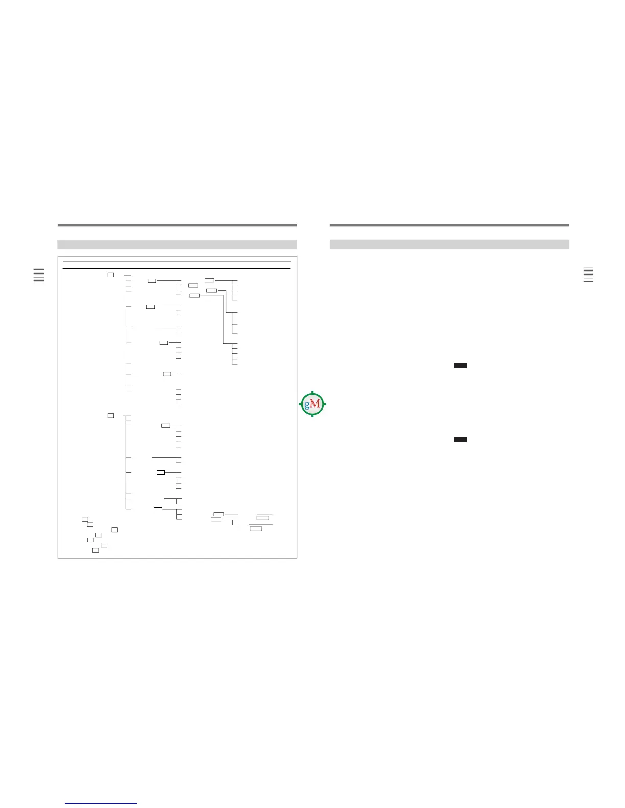
[C1] INPUT CONFIGURATION menu (1/2)
Set input signal data for each channel.
xxCH: Current channel is indicated. To change the
channel, enter a channel number with the numeric
keypad. The settings below will be stored as
information about the signal to be connected to this
channel.
FORMAT... : Select the input signal type. ÷[C11]
SLOT NO: Enter the slot number.
INPUT NO: Enter the input connector number.
YC SEP... : Select Y/C separation filter. ÷[C12]
SYNC MODE: Select the sync signal.
INT: Use an internal sync signal.
EXT: Use an external sync signal.
SCREEN MODE... : Select the scan size. ÷[C13]
SAFE AREA DISPLAY: Choose whether or not to
display the safe area (OFF or ON).
MODE... : Select the display mode for safe area.
÷[C14]
APERTURE: Choose whether to use aperture
adjustment or not (OFF or ON).
APERTURE VALUE: Enter the aperture adjustment
value (0 to 200).
[C1] INPUT CONFIGURATION menu (2/2)
Set input signal data for each channel.
xxCH: Current channel is indicated. To change the
channel, enter a channel number with the numeric
keypad. The settings below will be stored as
information about the signal to be connected to this
channel.
FILTER... : Switch the filter operation (OFF or ON)
when the monochrome display is selected.
CHANNEL NAME... : Give the channel a name.
÷ [C15]
Setting Lists in the INPUT CONFIGURATION Menu
CONTROL: Use if either PRESET or CH SET
values are used for the CONTRAST/BRIGHT/
CHROMA/PHASE settings.
PRESET: Use values common to all channels.
CH SET: Use individual values for each channel.
COLOR TEMP...: Set the color temperature.
÷ [C16]
H PHASE: Set the horizontal picture position (–128 to
+127).
1125/60I SYSTEM: Select the number of active
scanning lines per frame. When the HD SDI signal
is input, the number of active scanning lines is
selected automatically.
1080I: The active scanning lines are 1080 lines
1035I: The active scanning lines are 1035 lines.
COPY FROM... : Select a method for copying data
from elsewhere. ÷[C17]
Note
For H PHASE data, if a value above or below the
allowable range is entered, the monitor will not
operate correctly.
[C11] FORMAT menu
Select the signal format.
COMPOSITE... : Analog composite signal ÷ [C111]
YC... : Analog Y/C signal ÷ [C111]
COMPONENT... : Analog component or RGB signal
÷ [C112]
SDI... : Serial digital signal ÷ [C113]
Note
If there is no input connector or decoder corresponding
to a format, that format will not be selectable (the
cursor will skip over that item).
[C111] COMPOSITE menu/YC menu
Select the format of a composite or Y/C signal.
NTSC: SETUP 7.5 or 0.
PAL: S (simple) or D (delay)
PAL-M: S (simple) or D (delay)
SECAM (for the COMPOSITE menu only)
AUTO: The format of the input signal is detected and
switched automatically.
1)
1) It will take a few seconds to detect the format of an input
signal when AUTO is selected. It is recommended that a
particular format be selected if it is determined.
(continued)