3-1
BVM-D32E1WA/D32E1WE/D32E1WU
Section 3
Set-Up Adjustment
. Setting the INPUT CONFIGURATION Menu
Unless specified otherwise, set the INPUT CONFIGURA-
TION menu of the SETUP menu as follows.
FORMAT.......................... YPBPR 1080
SLOT NO.......................... 6
INPUT No......................... 1, 2, 3
SYNC MODE ................... INT
SCREEN MODE .............. 16 : 9 NOR
SALF AREA DISPLAY ... OFF
SALF AREA MODE ........ 16 : 9_88%
APERTURE...................... OFF
APERTURE VALUE ....... 100
CHANNEL NAME .......... PROG
CONTROL ....................... CH SET
COLOR TEMP ................. STD
H PHASE .......................... 000
H SYNC
V SYNC
RTS
GND
NC
TXD
+5V
RXD
1
2
3
4
5
6
7
8
FG
TXD
RXD
RTS
CTS
NC
GND
NC
NC
DTR
NC
1
2
3
4
5
6
7
8
9-19
20
21-25
..
..
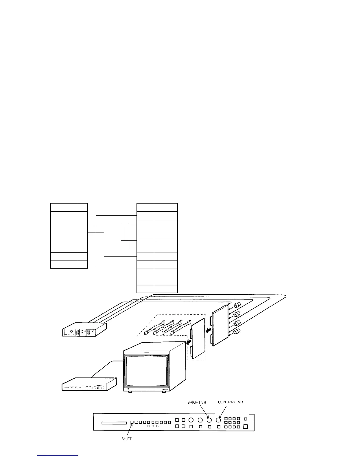
. Connection Diagram
Y/G terminal
P
B
/B terminal
P
R
/R terminal
SYNC terminal
75Ω terminater x 4
BK board
Extension board/cable kit
(Parts code : A-1394-806-B)
3-1. Set-Up Adjustment When CRT is
Replaced
This section describes adjustments to be performed when
the CRT has been replaced.
Preparations
..
..
. Required tools and measuring instruments
1. Signal generator
..
..
. 1125 (1035) : SMPTE240M standard or
BTA S-001A standard
..
..
. 1125 (1080) : SMPTE274M standard
..
..
. 525P : SMPTE293M standard or
BTA T-1004 standard
..
..
. 1250 : SMPTE295M standard
2. Oscilloscope
3. Color analyzer (Minolta CA-100)
4. Cables of the following specifications for connecting
the CA-100 RS-232C terminal and OPTION terminal
of the monitor.
BVM Option connector side
Mini DIN 8pin
CA-100 RS-232C connector side
D Sub 25-pin (Male)
BKM-10R Control Panel
Component signal generator
SLOT No. 6
BKM-10R
BVM-D32E1WA/D32E1WE/D32E1WU