3-10
BVM-D32E1WA/D32E1WE/D32E1WU
[Convergence Adjustment]
• Preparations
1. Set SCREEN MODE to 16:9 NORM at the INPUT
CONFIGURATION menu of the SETUP menu.
2. Input the HD (1125) cross-hatch signal.
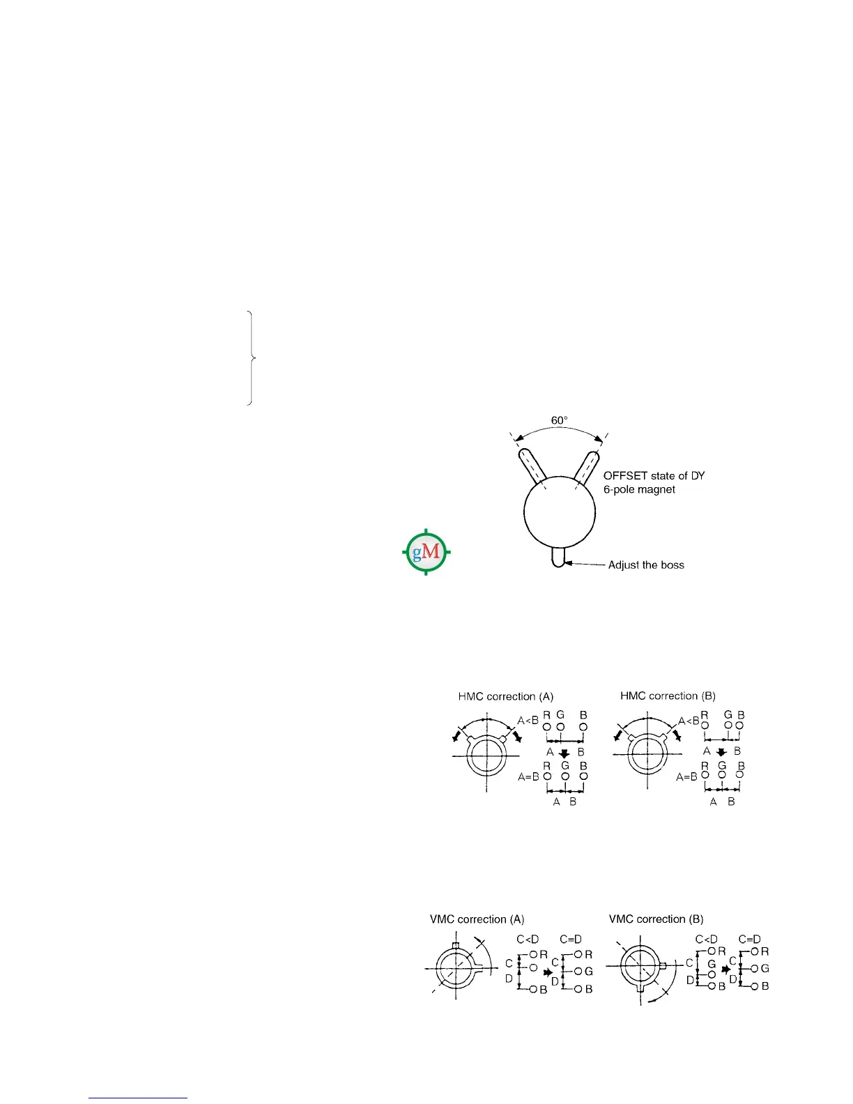
3. Set the 4-pole magnet of the DY to the OFFSET state in the
case.
Confirm that the H. STAT data is in the pre-set value (128)
and the V. STAT data is also in the pre-set value (128).
Set the user’s menu ALIGNMENT V. STATIC CONV., V.
CONV. TOP., V. CONV. BOT, and H. STATIC CONV. to
100.
Confirm that the H. STAT data is in the pre-set value (128) .
Note: The H. STAT adjustment menu is located in the
lower layer of the E board menu of the MAINTE-
NANCE menu.
Fig. 1-12
. HMC and VMC correction by the 6-pole magnet
1. HMC (horizontal mis-convergence) correction by the
6-pole magnet and movement electronic beam
Fig. 1-13
2. Correction of 6-pole magnet VMC (vertical mis-conver-
gence) and movement of electronic beam
Fig. 1-14
18. Connect the MODE11 480/60P (15 kHz) signal to the
input.
19. Set SCREEN MODE to 16:9 NORM at the INPUT CON-
FIGURATION menu of the SETUP menu.
20. Perform the adjustments of steps 3 to 12.
21. Change the SCREEN MODE of the following modes as
well, and perform adjustments in the same way.
MODE12 525 16:9 UNDER SCAN
MODE13 525 4:3 NORMAL
MODE14 525 4:3 UNDER SCAN
• Common items for modes
DY inclination
Up/down V PIN distortion
H CENTER BOW
H MID PIN
H CORNER PIN
• Items differing between modes
H TRP
V CENTER
H LIN BAL
H LIN
V LIN BAL
H KEY BAL
H KEY
H PIN BAL
H PIN
V SIZE
H SIZE
V LIN
H CENTER
22. Change the SCREEN MODE of modes 17 to 32 as
well, and perform adjustments in the same way.
(Refer to Table 1 (page 3-3))
Copy the data of MODE11
480/60P (15 kHz)
16:9 NORM.