50
Chapter 2 Menu
[C61] CONV FINE ADJUST menu (BVM-
D32E1WU/D32E1WE/D32E1WA only)
Adjust the convergence finely at each adjustment point
on the screen with the MANUAL knobs.
The signal format and screen size for the adjustment
are displayed on the top of the screen.
ADJUST... : Adjust the convergence. ÷[C611] (It
may take some time to change to the next menu.)
Use appropriate knobs and buttons in each
adjustment as described below.
H CONV: CONTRAST KNOB: Adjust the
horizontal convergence with the CONTRAST
knob.
H G CONV: BRIGHT KNOB: Adjust the
horizontal convergence with the BRIGHT
knob.
V CONV: CHROMA KNOB: Adjust the vertical
convergence with the CHROMA knob.
V G CONV: PHASE KNOB: Adjust the vertical
convergence with the PHASE knob.
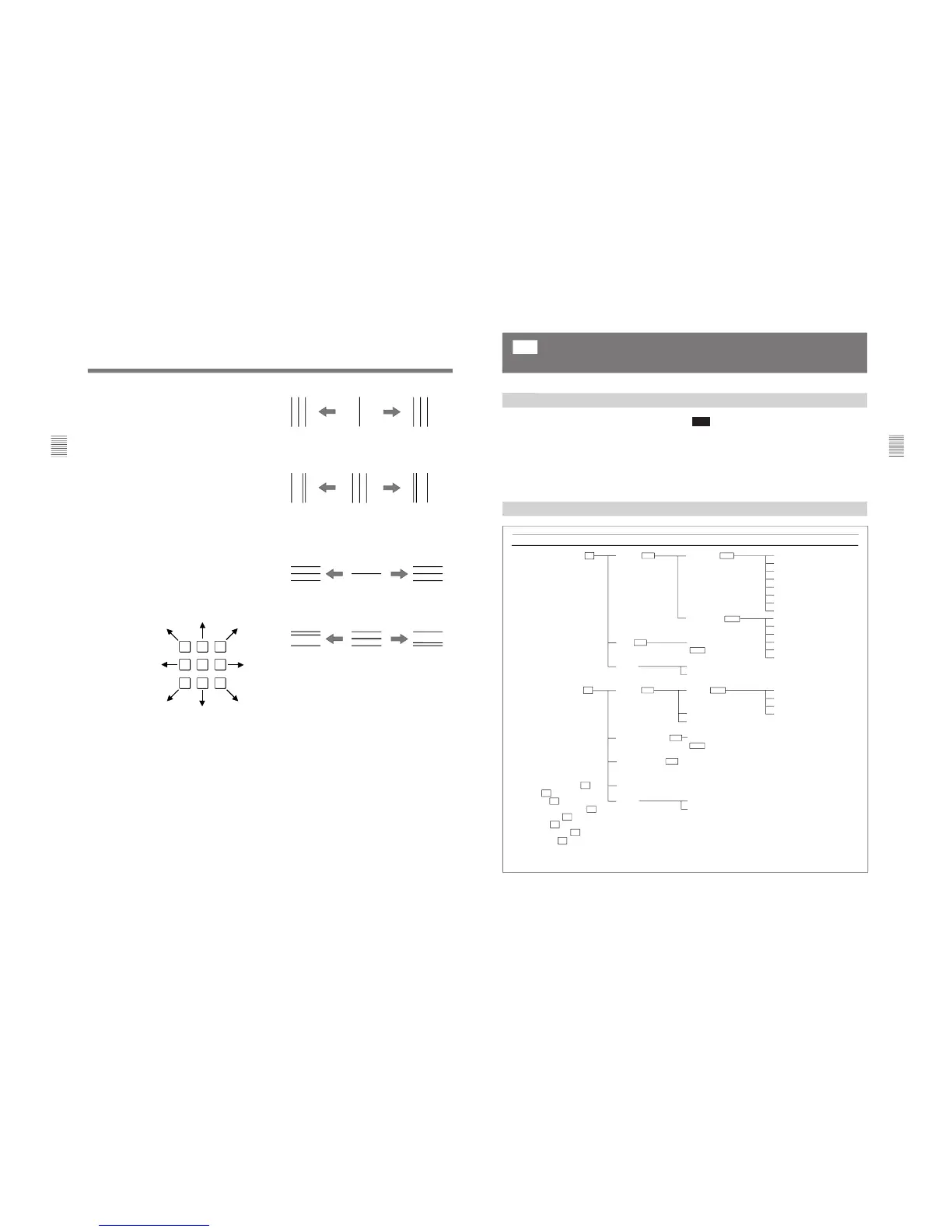
CURSOR POSITION: 10KEY: Move the cursor
using the numeric keypad (except the 5 button)
as illustrated below. Turn on/off the cursor
using the 5 button.
TO CANCEL: MENU KEY: Press the MENU
button to clear the adjusted data and return to
the previous menu.
TO CONFIRM: ENTER KEY: Press the
ENTER or Ent button to confirm the adjusted
data.
[C611] ADJUST menu
Adjust the convergence at the cursor position using the
CONTRAST (H CONV), BRIGHT (H G CONV),
CHROMA (V CONV) and PHASE (V G CONV)
knobs. Move the cursor using the numeric keypad.
H CONV: Turn the CONTRAST knob clockwise to
move the R beam to the right and the B beam to the
left; counterclockwise to move the R beam to the
left and the B beam to the right.
H G CONV: Turn the BRIGHT knob clockwise to
move the G beam to the left; counterclockwise to
move the G beam to the right.
V CONV: Turn the CHROMA knob clockwise to
move the R beam upward and the B beam
downward; counterclockwise to move the R beam
downward and the B beam upward.
V G CONV: Turn the PHASE knob clockwise to
move the G beam downward; counterclockwise to
move the G beam upward.
To reset the convergence to the condition before
adjustment
You can reset the adjusted condition to the one before
adjustment by pressing the corresponding MANUAL
button.
To finish the adjustment
Press the ENTER or Ent button. The adjusted data is
stored in the memory and the screen returns to the
CONV FINE ADJUST menu ([C61]). (It may take
some time to change to the previous menu.)
To cancel the adjustment
Press the MENU button. The adjusted data is cleared
and the screen returns to [C61]. (It may take some
time to change to the previous menu.)
When you want to erase characters from the screen
while adjusting the convergence
Press the [F1] button. The characters disappear. To
display characters, press the [F1] button again.
51
Chapter 2 Menu
Structure of the WHITE UNIFORMITY Menu
The following two adjustments can be performed using
the WHITE UNIFORMITY menu, by making the
white in the picture as uniform as possible.
•Correcting the shift of beam landing caused by the
earth’s magnetism (LANDING ADJUST menu)
•Adjusting the color unevenness of the CRT
(DIGITAL UNIFORMITY menu)
Overview
[C7]
Adjusting Beam Landing and Digital Uniformity (SET UP 7) — WHITE
UNIFORMITY Menu
(BVM-D24E1WU/D24E1WE/D24E1WA/D32E1WU/D32E1WE/D32E1WA
only)