13
Chapter 1 Overview
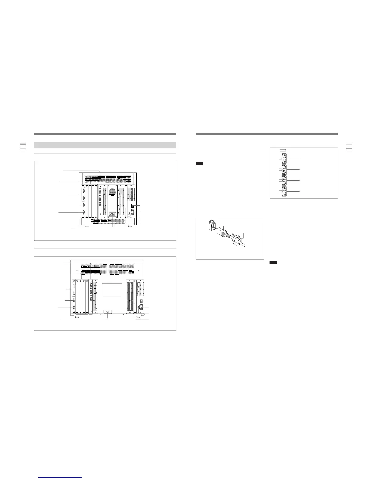
1 MAIN POWER switch
When turned on, the monitor enters operation mode.
By setting in the SYSTEM CONFIGURATION menu,
the monitor can also be set to enter standby mode
when the MAIN POWER switch is turned on.
Note
When the monitor is turned on, “INITIALIZING” is
displayed. While it is displayed, the monitor cannot
accept commands from the BKM-10R/11R Monitor
Control Unit or the equipment connected to the serial
REMOTE 1 connector.
For information about the SYSTEM CONFIGURATION
menu, see “ [C4] Setting the Channel Selection Method,
Power-Up Conditions and Decoder (SET UP 4) — SYSTEM
CONFIGURATION Menu” on page 44.
2 AC IN socket (3-pin)
Connects the monitor to an AC power source, via the
supplied AC power cord.
3 Fuse
Use a T4AH fuse.
4 Deflection option slot
For the BVM-D24E1WU/D24E1WE/D24E1WA/
D32E1WU/D32E1WE/D32E1WA, the digital
uniformity adaptor has been installed at the factory.
For the BVM-D20F1U/D20F1E/D20F1A, this slot is
provided for future use.
Attach the AC Plug holder to the AC power cord, and
connect it to the AC IN socket so that the cord does not
come loose.
AC Plug holder (supplied)
AC power cord (supplied)
5 Analog input/output connectors
GBR signals, component signals (Y/P
B/PR), or
composite sync signals can be fed in the IN connectors.
The type of signal applied to each connector is set with
the INPUT CONFIGURATION menu. The OUT
connectors are used for loop-through output of the
input signal. When not using loop-through, connect a
75-ohm terminator (not supplied) to the OUT
connectors.
For information about the INPUT CONFIGURATION menu,
see “ [C1] Setting the Input Configuration (SET UP 1) —
INPUT CONFIGURATION Menu” on page 35.
6 Input option slots
The monitor may be fitted with optional decoder
adaptors.
Note
The BKM-41HD and BKM-42HD use two input
option slots.
Y/G connectors (BNC)
P
B
/B connectors (BNC)
P
R
/R connectors (BNC)
SYNC connectors (BNC)