3-8
BVM-D32E1WA/D32E1WE/D32E1WU
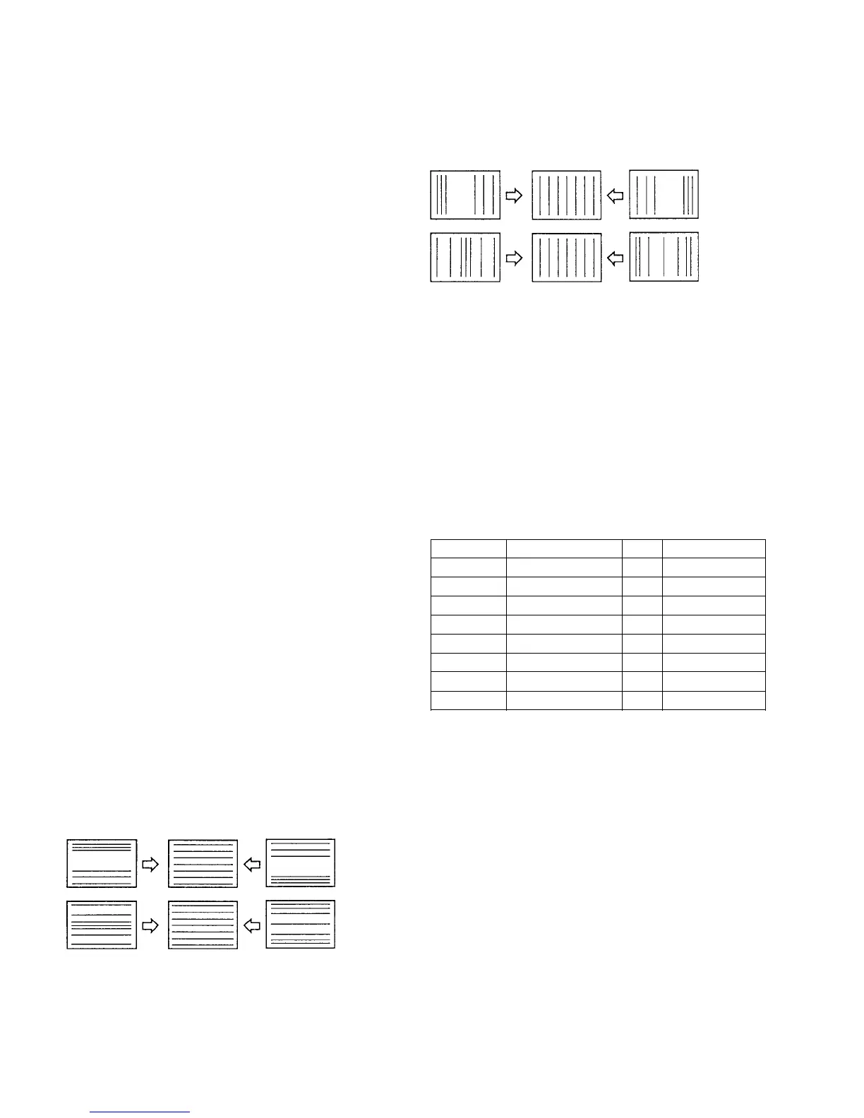
Fig. 1-9
10. Adjust the H KEY BAL, H KEY, H PIN BAL, and H
PIN data so that the trapezoid distortion and PIN
distortion at the side disappear as shown in Fig. 1-10.
11. Adjust the H CENTER BOW, H MID PIN, and H
CORNER PIN data as shown in Fig. 1-11.
12. Repeat the above adjustments and optimize the
horizontal and vertical linearities.
13. Change the SCREEN MODE for the following modes
as well, and perform adjustments in the same way.
MODE2 1125 16:9 UNDER SCAN
MODE3 1035/60i (33kHz) 16:9 NORMAL
MODE4 1125 16:9 UNDER SCAN
MODE7 480/60P (31kHz) 16:9 NORMAL
MODE8 525 16:9 UNDER SCAN
MODE9 525 4:3 NORMAL
MODE10 525 4:3 UNDER SCAN
MODE15 1080/48i (27kHz) 16:9 NORMAL
MODE16 1125 16:9 UNDER SCAN
H LIN BAL
H LIN
9. Adjust the H SIZE, H LIN BAL, and H LIN data as
shown in Fig. 1-9.
[Linearity Adjustment]
Note: The following adjustment menu is located inside the
E BOARD menu of the MAINTENANCE menu.
V CENTER H CENTER BOW
H LIN BAL H MID PIN
H LIN H CORNER PIN
V LIN BAL V SIZE
H KEY BAL H LINE
H KEY V LIN
H PIN BAL H CENTER
H PIN
1. Input the HD (1125) cross-hatch signal.
2. Select the 16:9 NORM of the SCREEN mode using
the INPUT CONFIGURATION menu of the SETUP
menu.
3. Confirm that there exists no DY inclination, no V PIN
cushion distortion in the top and bottom and no
horizontal trapezoidal distortions on screen. If there
exits any errors, remove the errors as follows.
DY inclination :
Adjust the DY inclination
V PIN cushion distortion in the top and bottom:
DY up/down neck twist
Horizontal trapezoidal distortion :
Adjust by H. TRP VR of the DY
(If they are adjusted extremely, the convergence can
be adversely affected. In such a case, select the green
single color for this adjustment.)
4. Input the HD (1125) monoscope signal.
5. Adjust the H CENTER data and adjust the horizontal
center of the image.
6. Adjust the V CENTER data and adjust the vertical
center of the image.
7. Input the HD (1125) cross-hatch signal.
8. Adjust the VSIZE, V LIN BAL, and V LIN data as
shown in Fig. 1-8.
V LIN BAL
V LIN AMP
Fig. 1-8