5-8
BVM-D32E1WA/D32E1WE/D32E1WU
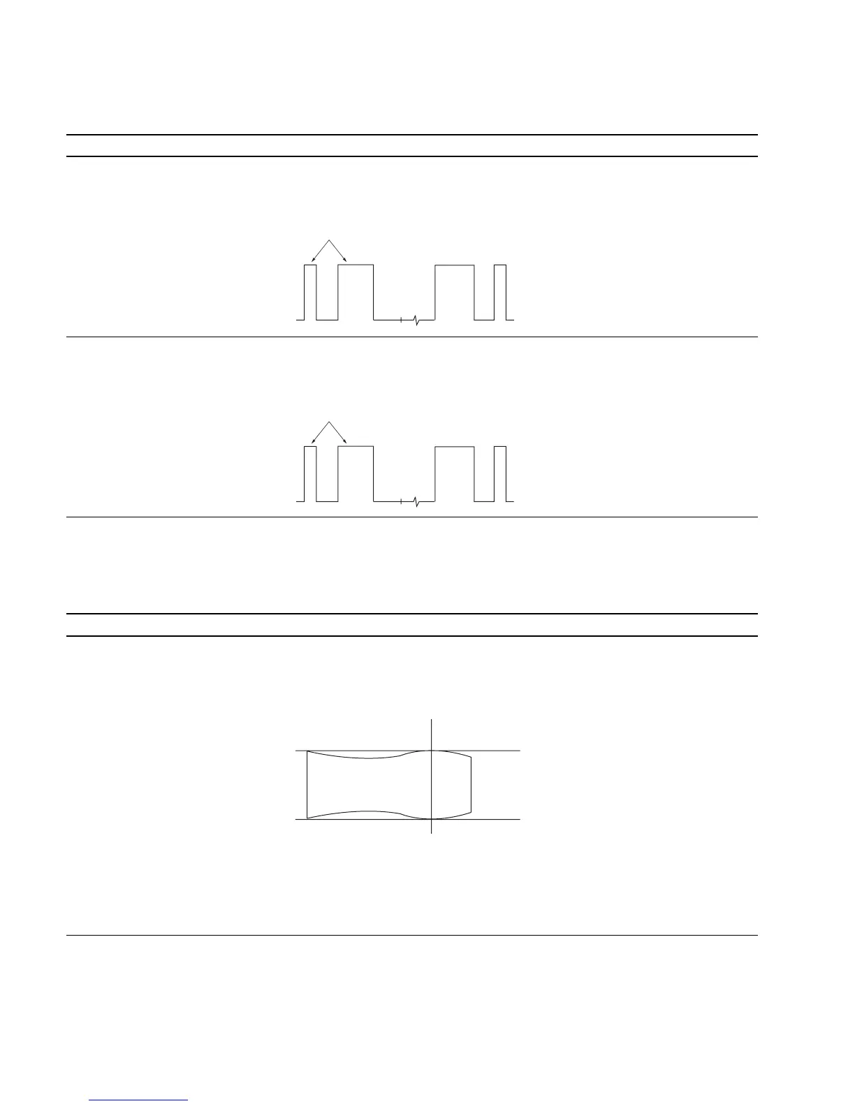
10. RGB 100 IRE Adjustment
Adjustment Standard Adjusting Point
Step 1
..
..
. Input 100 IRE RGB signal. The 100 IRE level of the TP105 output is equal to The adjustment menu is
..
..
. Connect an oscilloscope to TP105. the 100 IRE pulse. R 100 IRE located inside
the BK BOARD menu of
the MAINTENANCE menu.
Step 2
..
..
. Like step 1, connect oscilloscopes The 100 IRE levels of TP305 and TP505 are The adjustment menus are
to TP305 and TP505. equal to the 100 IRE pulse. G 100 IRE and B 100 IRE
located inside the BK BOARD
menu of the MAINTENANCE
menu.
11. Frequency Characteristics Adjustment
Note: Do not adjust the BK board with the extension board and cable connected in this adjustment.
Adjustment Standard Adjusting Point
Step 1
• Input the 0 to 40 MHz sweep signal The 0 to 30 MHz range of the TP2 (R) output 1 CV100 (B-2) BK board
with the RGB signal input. waveform is flat : If outside the standard:
(MARKER ON) 1 RV100 (B-2) BK board
• Rotate RV100 fully in the clockwise
direction (2).
• Connect an oscilloscope to TP2 (R)
of the C board using a 100:1 FET
probe.
• Adjust CV100 so that the waveform
satisfies the standard.
If unadjustablecompletely using
CV100, adjust to satisfy the standard
while tracking with RV100 and CV100.
Note: Adjust so that the 25 MHz marker becomes 0
dB, and check if the above standard is satis-
fied.
Equalize
Equalize
25MHz
0
+0.5
dB
_1.0