5-6
BVM-D32E1WA/D32E1WE/D32E1WU
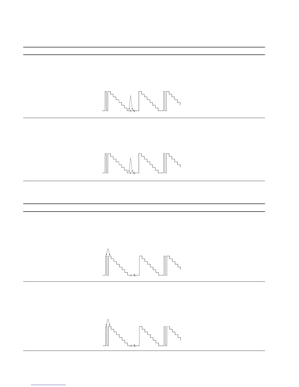
5. Setup Adjustment
Adjustment Standard Adjusting Point
Step 1
..
..
. Input only the Y signal of color bar The black level and setup signal level of The adjustment menu is
signal (1125/60 Hz 2:1). TP105 are equal: R SETUP located inside
(Cut off the B-Y and R-Y signals.) Level difference : 0 ± 2 mV the BK BOARD menu of
..
..
. Connect an oscilloscope to TP105. the MAINTENANCE menu.
Step 2
..
..
. Like step 1, connect oscilloscopes The black levels and setup signal levels of The adjustment menus are
to TP305 and TP505. TP305 and TP505 are equal: G SETUP and B SETUP
Level difference : 0 ± 2 mV located inside the BK BOARD
menu of the MAINTENANCE
menu.
6. 100 IRE Adjustment
Adjustment Standard Adjusting Point
Step 1
..
..
. Input color bar signal The 100 IRE level and 100 IRE pulse level of The adjustment menu is
(1125/60 Hz 2:1). the TP105 output are equal: R 100 IRE located inside
..
..
. Connect an oscilloscope to TP105. Level difference : 0 ± 2 mV the BK BOARD menu of
the MAINTENANCE menu.
Step 2
..
..
. Like step 1, connect oscilloscopes The 100 IRE levels and 100 IRE pulse levels of The adjustment menus are
to TP305 and TP505. the TP305 and TP505 outputs are equal: G 100 IRE and B 100 IRE
Level difference : 0 ± 2 mV located inside the BK BOARD
menu of the MAINTENANCE
menu.
Adjust
Adjust
Adjust
Adjust