5-5
BVM-D32E1WA/D32E1WE/D32E1WU
3. Pulse Level Adjustment
Adjustment Standard Adjusting Point
Step 1
..
..
. Input color bar signal The output waveform of TP505 is flat: The adjustment menu is
(1125/60 Hz 2:1). Level difference : 0 ± 10 mV PB LEVEL located
..
..
. Set the CHROMA data to 1000 inside the BK BOARD menu of
using the CHROMA knob. the MAINTENANCE menu.
(Note: At CONTROL PRESET)
..
..
. Connect an oscilloscope to TP505.
Step 2
..
..
. Connect an oscilloscope to TP105. The output waveform of TP105 is flat: The adjustment menu is
Level difference : 0 ± 10 mV PR LEVEL located
inside the BK BOARD menu of
the MAINTENANCE menu.
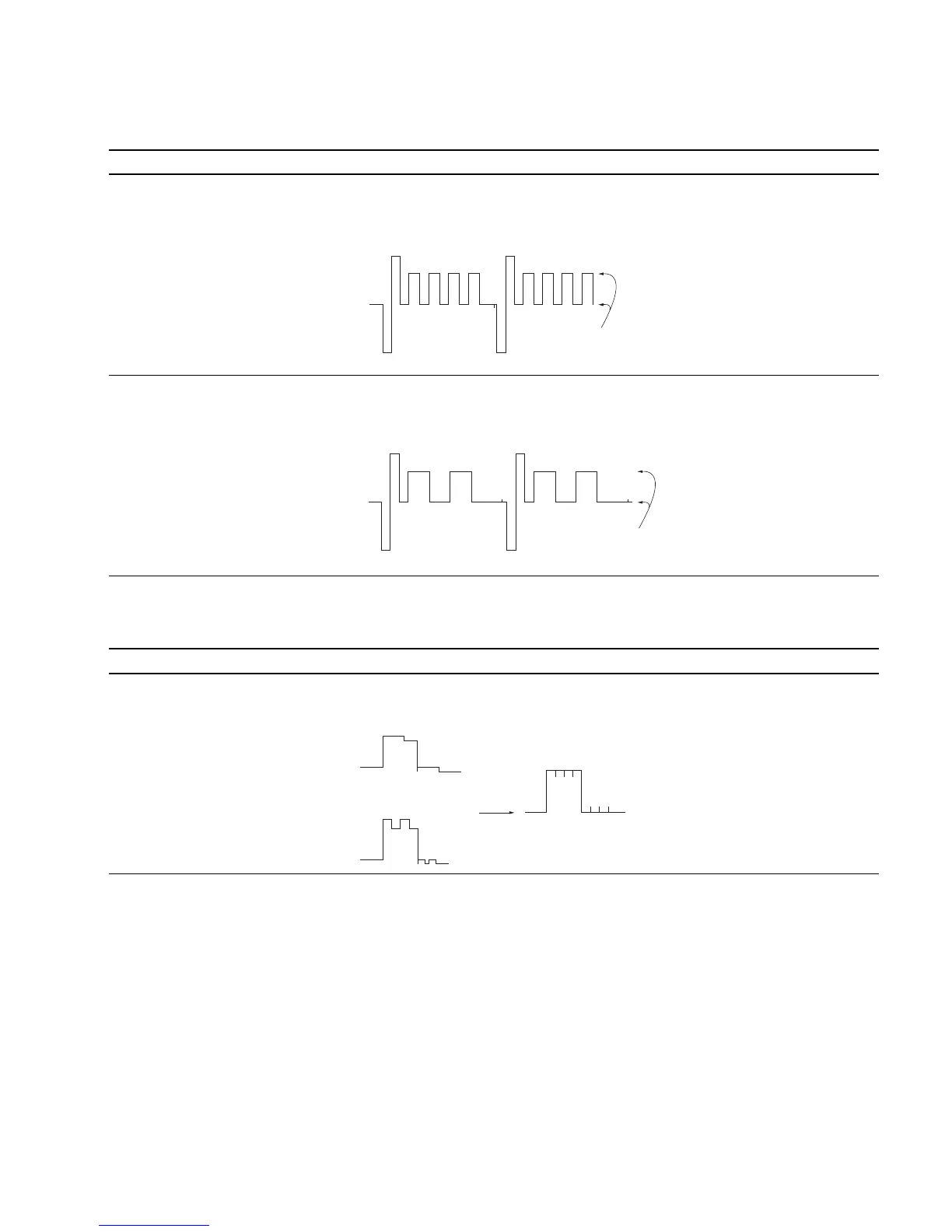
4. R-Y gain, B-Y gain Adjustment
Adjustment Standard Adjusting Point
..
..
. Input color bar signal The GREEN waveform of TP305 is flat: The adjustment menus are
(1125/60 Hz 2:1). Level difference : 0 ± 10 mV R-Y GAIN, B-Y GAIN located
..
..
. Set the CHROMA data to 1000 inside the BK BOARD menu of
using the CHROMA knob. the MAINTENANCE menu.
(Note: At CONTROL PRESET)
..
..
. Connect an oscilloscope to TP305.
Flatten
Flatten
R-Y GAIN (+)
B-Y GAIN (+)
Flatten