5-7
BVM-D32E1WA/D32E1WE/D32E1WU
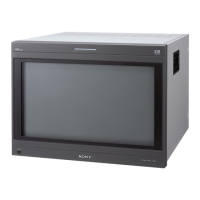
7. Bias Ref Adjustment
Adjustment Standard Adjusting Point
..
..
. Set CONTRAST to 2048 at The all white peak of the TP306 output is The adjustment menu is
the BK BOARD menu of equal to the BIAS REF pulse: BIAS REF located inside
the MAINTENANCE menu. Level difference : 0 ± 5 mV the BK BOARD menu of
..
..
. Input the 20 IRE all white signal. the MAINTENANCE menu.
..
..
. Connect an oscilloscope to TP306.
Note: Check the waveform in the V period.
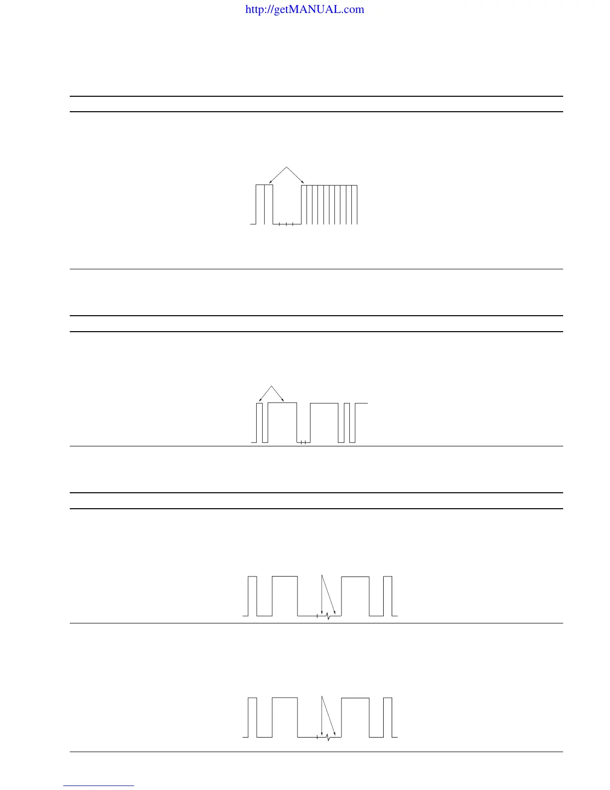
8. Drive Ref Adjustment
Adjustment Standard Adjusting Point
..
..
. Set CONTRAST to 2048 at The all white peak of the TP306 output is The adjustment menu is
the BK BOARD menu of equal to the DRIVE REF pulse: DRIVE REF located inside
the MAINTENANCE menu. Level difference : 0 ± 5 mV the BK BOARD menu of
..
..
. Input the 100 IRE all white signal. the MAINTENANCE menu.
..
..
. Connect an oscilloscope to TP306.
9. RGB Setup Adjustment
Adjustment Standard Adjusting Point
Step 1
..
..
. Input the RGB signal of 100 IRE. The black level of the TP105 output is equal to The adjustment menu is
..
..
. Connect an oscilloscope to TP105. the SETUP signal level: R SETUP located inside
Level difference : 0 ± 2 mV the BK BOARD menu of
the MAINTENANCE menu.
Step 2
• Like step 1, connect oscilloscopes The black levels of the TP305 and TP505 outputs are The adjustment menus are
to TP305 and TP505. equal to the SETUP signal level: G SETUP and B SETUP
Level difference : 0 ± 2 mV located inside the BK BOARD
menu of the MAINTENANCE
menu.
Equalize
Equalize
Equalize
Equalize
http://getMANUAL.com