3-13
BVM-D32E1WA/D32E1WE/D32E1WU
[G2 Adjustment]
Note: The G2 REF adjustment menu is located inside the
BK BOARD menu of the MAINTENANCE menu.
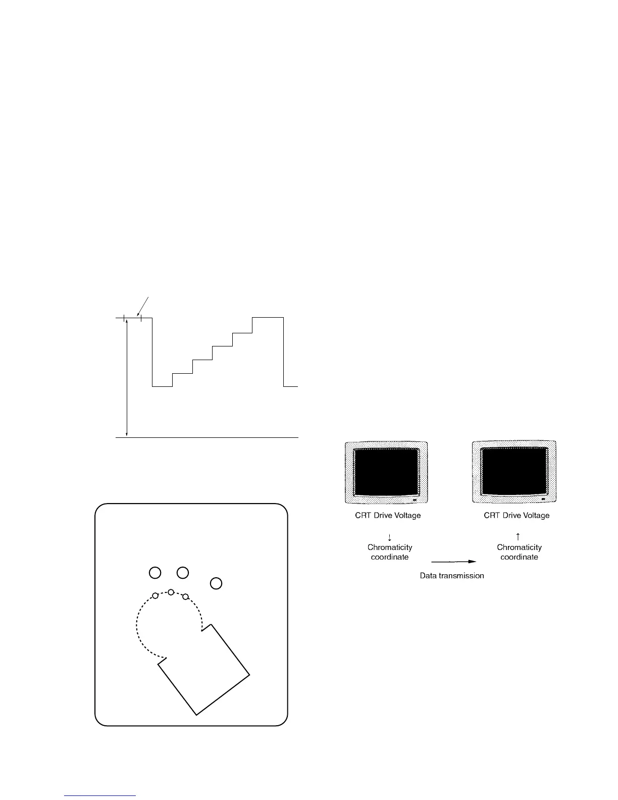
1. Input the HD (1125) color bar signal. (CHROMA:
OFF state)
2. Connect the probe of the oscilloscope to each R, G, B
cathode (TP2, 3, 4) of the C board, and check the DC
voltages of the color bar signal pedestal portions.
(20V/Div)
3. Connect the probe of the oscilloscope to the cathode
with the highest pedestal DC voltage.
4. Adjust G2 REF so that the DC voltage at the pedestal
becomes the value as shown below.
Specifications : 97.5 ± 2.5 V
Pedestal
DC
0 (V
DC
)
97.5 ± 2.5 (V
DC
)
Fig. 1-20
(CHROMA of color bar : OFF state)
GIG
H-1
H-2
GND
KR
KG
KB
G2
GIR
TP2 TP3
TP4
C board – Side B –
Fig. 1-21
[White Balance Adjustment]
Note: Perform the landing adjustment and the digital
uniformity adjustment before the white balance
adjustment as much as possible.
1. Outline of Adjustments and Calibration of the Color
Analyzer Used for Adjustments
Perform the following adjustments.
1.1 Obtaining the Parameters for Converting the RGB
Drive Voltage of the CRT to the Chromaticity Coordinate
This monitor comes equipped with a function to copy
color temperature between several monitors.
Since the CRT drive voltage depends on each individ-
ual CRT. The same color temperature cannot be
obtained even if the same drive voltage is supplied to
several monitors. Consequently, to copy a certain color
temperature between several monitors, there is a need
to transmit data which does not depend on the CRT
using the xyY chromaticity coordinate.
When the SYSTEM/COLOR TEMP/FACTORY ADJ
menu of the MAINTENANCE menu is selected and
executed, the D93 color temperature will automatically
be adjusted, and at the same time, the parameters for
converting the drive voltage and chromaticity coordi-
nate will be created. Use these parameters when
copying color temperature to other monitors and
copying color temperature to the memory card.
Fig. 1-22
1.2 D65 Color Temperature Adjustment
1.3 Copying Color Temperature Data D93 to Color
Temperature STD, COLOR1, COLOR2, and AUX
. Calibration of color analyzer
Generally, when measuring the color temperature of a
certain monitor using several color analyzers, these color
analyzers will show different measured values. The
measured values will also change with time.
Use the color analyzers for this adjustment after calibrat-
ing them so that they will show the correct measured
values at the following chromaticity coordinate.