3-14
BVM-D32E1WA/D32E1WE/D32E1WU
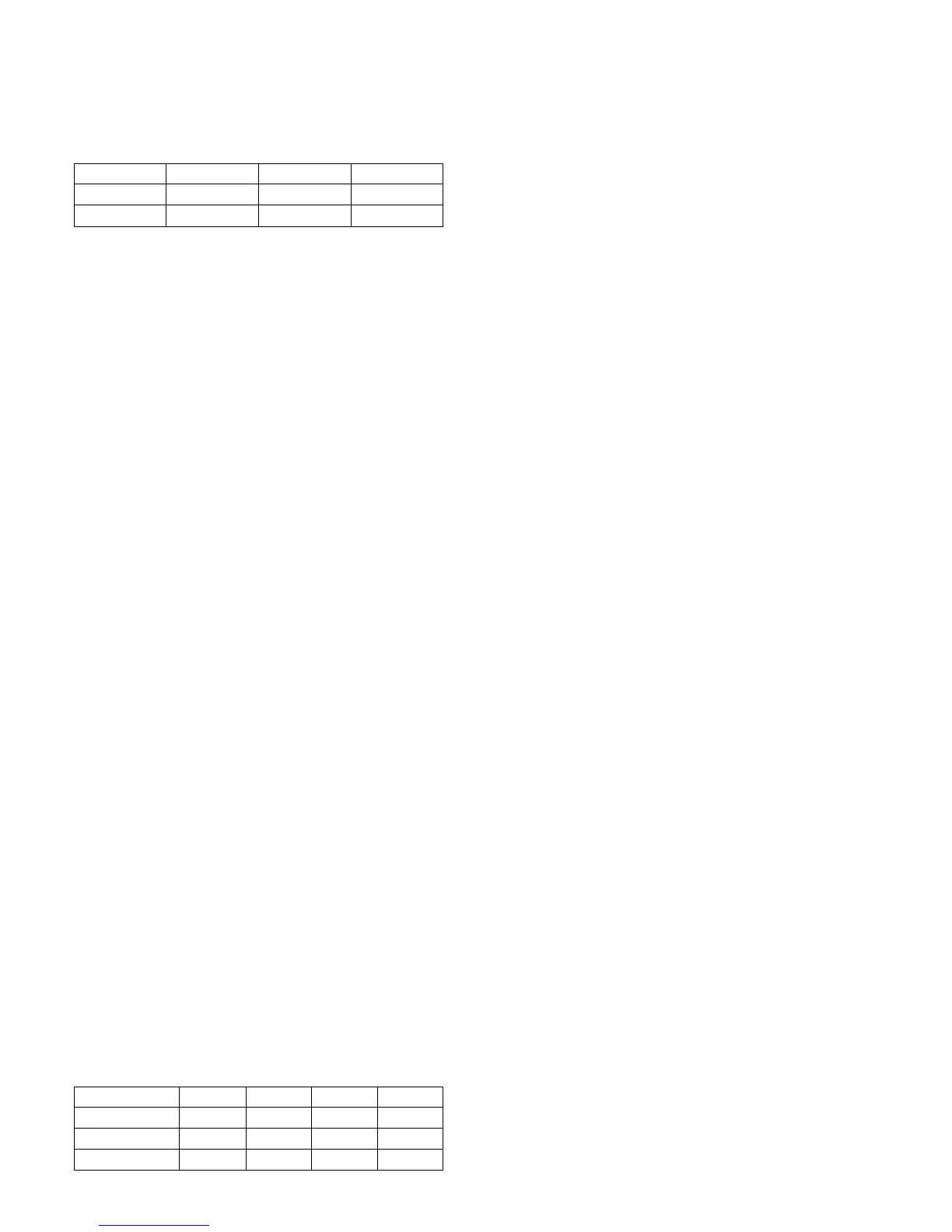
D93
283
297
D65
313
329
D56
331
346
X
Y
2. Preparations for Adjustments
2.1 Input the HD signal (1125) into the G/Y input terminal
of the BK board to display it on the screen.
2.2 Connect the RS-232C terminal of CA-100 and the
OPTION terminal of the monitor using the cables
indicated at Required Tools and Measuring Instru-
ments (see page 3-1).
2.3 Set CA-100 as follows, and attach the measuring probe
of CA-100 to the center of the CRT screen.
Display mode : xyY mode
Baud Rate : 9600
3. Select SET UP menu of MAINTENANCE menu.
4. Select the SYSTEM/COLOR TEMP menu of the
MAINTENANCE menu.
5. Select D93 of COLOR TEMP, cover the CRT screen
with a blackout cloth, select FACTORY SET, and start
automatic adjustments.
After adjustment, confirm the correct measured value
of the color analyzers.
6. Select D65 of COLOR TEMP, and then select the
PROBE menu. After selecting D65, cover the CRT
screen with a blackout cloth, and select START to start
automatic adjustments.
After adjustment, confirm the correct measured value
of the color analyzers.
7. Select the SYSTEM/COLOR TEMP/COPY/OTHER
VALUE menu of the MAINTENANCE menu.
8. Select STD of COLOR TEMP, select the value shown
in the following table, and copy the color temperature
data to STD.
9. Select COLOR1 of COLORTEMP, select the value
shown in the following table, and copy the color
temperature data to COLOR1.
10. Select COLOR2 of COLORTEMP, select the value
shown in the following table, and copy the color
temperature data to COLOR2.
11. Select AUX of COLORTEMP, select the value shown
in the following tabel, and copy the color temperature
data to AUX.
STD
D65
D65
D93
COL 1
D93
D93
D65
COL 2
D56
D65
D93
U/C
AEP, AUS
J
AUX
D65
D65
D93
Set the measured value of the color analyzers to the same
value as the correct measured value.
Low light : 1.9 (cd/m
2
) 20 IRE
High light :70.0 (cd/m
2
) 100 IRE