11
Chapter 1 Overview
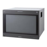
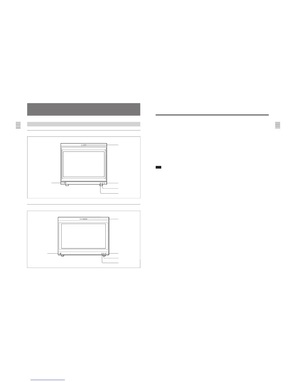
1 Tally lamp
With factory settings, the tally lamp lights when pins
No. 8 and No. 9 of the REMOTE 2 connector on the
rear panel are shorted. By changing the setting in the
REMOTE menu, different pins on the remote
connector can be used to control the tally lamp.
For information about the REMOTE menu, see “[C2]
Assigning the Remote Control Functions (SET UP 2)
— REMOTE Menu” on page 40.
2 POWER lamp
Lights when the monitor is put into operation mode
from standby mode (see STANDBY lamp 3) by
pressing the POWER switch of the BKM-10R/11R.
Note
When the STANDBY lamp 3 is blinking, the monitor
cannot be put into operation mode (internal data
initialization is taking place). Wait until the
STANDBY lamp 3 is steadily lit.
3 STANDBY lamp
Lights when the monitor is in standby mode. The
monitor will be in standby mode under the following
conditions:
•The MAIN POWER switch (on the rear panel) is
turned on (the STANDBY lamp will blink for a few
moments after the switch is turned on, then will
light).
•The monitor is changed from operation mode to
standby mode by external control.
4 OVER LOAD lamp
Lights to warn of CRT overload.
When the OVER LOAD lamp is lit, use the unit with
the contrast or brightness reduced.
5 OPTION connector
Used to connect the BKM-11R Monitor Control Unit
or a auto setup probe (BKM-14L, etc).