5-9
BVM-D32E1WA/D32E1WE/D32E1WU
Adjustment Standard Adjusting Point
Step 2
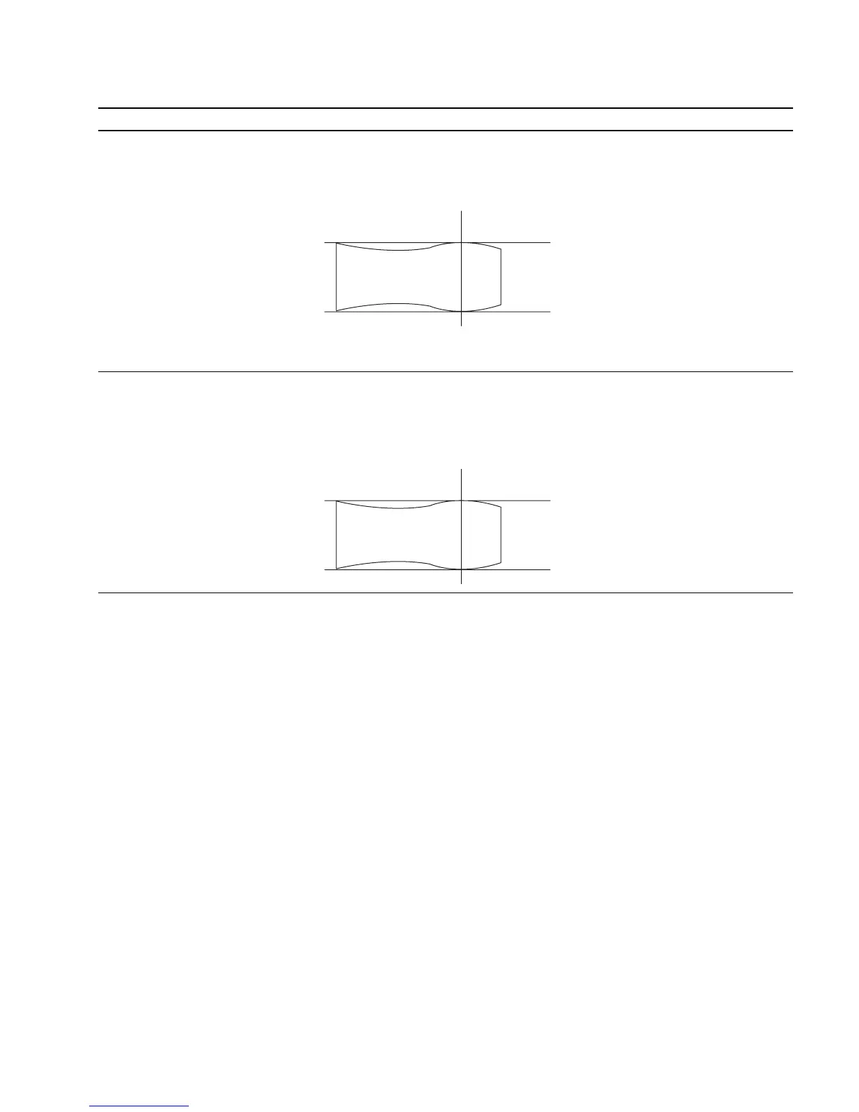
• Rotate RV300 fully in the clockwise The 0 to 30 MHz range of the TP3 (G) output 1 CV300 (D-2) BK board
direction (2). waveform is flat : If outside the standard:
• Connect an oscilloscope to TP3 (G) 1 RV300 (D-2) BK board
of the C board using a 100:1 FET
probe.
• Adjust CV300 so that the waveform
satisfies the standard.
If unadjustable completely using
CV300, adjust to satisfy the standard
while tracking with RV300 and CV300.
Step 3
• Rotate RV500 fully in the clockwise The 0 to 30 MHz range of the TP4 (B) output 1 CV500 (E-2) BK board
direction (2). waveform is flat : If outside the standard:
• Connect an oscilloscope to TP4 (B) 1 RV500 (E-2) BK board
of the C board using a 100:1 FET
probe.
• Adjust CV500 so that the waveform
satisfies the standard.
If unadjustable completely using
CV500, adjust to satisfy the standard
while tracking with RV500 and CV500.
12. Reference
Refer to 5-1. Basic Adjustments When Replacing CRT for details of the following adjustments.
G2 adjustment
White balance adjustment
25MHz
25MHz
0
+0.5
dB
_1.0
0
+0.5
dB
_1.0