3-12
BVM-D32E1WA/D32E1WE/D32E1WU
4. Adjust the V. STAT BOTTOM data then adjust the V.
STAT TOP data in this order so that the vertical mis-
convergence in the top and bottom of screen.
(Keep the V.STAT data to be 128, and do not change
it to any data other than 128.)
Note: The V. STATIC BOTTOM and the V. STAT. TOP
adjustment menus are located in the lower layer of
the E board menu of the MAINTENANCE menu.
5. If there exists any left-to-right asymmetrical areas,
insert the TLH correction plate into DY and so that the
mis-convergence is minimized.)
6. Copy the respective adjustment data into MODE1 to
MODE32. Then confirm the vertical and horizontal
convergence again. If any mis-convergence is noticed,
adjust the convergence again.
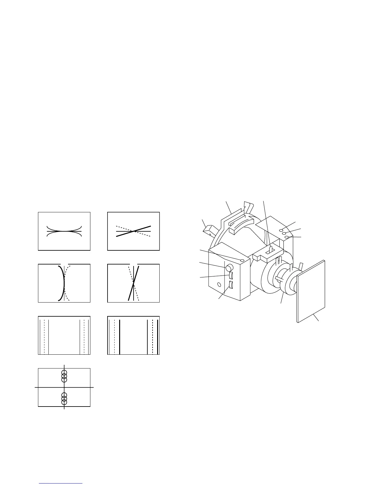
Deflection yoke
TLH
TLV
XBV
XCV
APH
Neck assy
C board
H.TRP
YCH
YBH
DY spacer
Fig. 1-19
[Convergence Adjustment]
• Preparation
1. Select the 16:9 NORM of the SCREEN mode using
the INPUT CONFIGURATION menu of the SETUP
menu.
2. Connect the MODE13 480/60i (15 kHz) cross-hatch
signal to input.
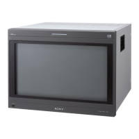
• Convergence adjustment
1. Minimize the vertical mis-convergence in the center at
the left-most end and at the right-most end of screen
using the DY correction reactors XBV and XCV.
2. Minimize the horizontal mis-convergence in the top
and the bottom of screen using the DY correction
reactors YCH and YBH.
3. Minimize the mis-convergence at the left-most end
and at the right-most end of screen using the DY
correction reactors APH and TLH.
XBV
R
B
G
R
B
G
XCV
B
R
G
R
B
APH
RBG R
R
B
B
G
G
R
B
G
YBH YCH
RB
G
RB
BR
G
V STAT TOP
V STAT BOTTOM
TLH
BRG RBG
Fig. 1-18