3-6
BVM-D32E1WA/D32E1WE/D32E1WU
. 480/60P (31 kHz/15 kHz) 16:9 NORMAL mode hori-
zontal blanking adjustment
1. Select 480 16:9 NORM of the SCREEN mode using the
INPUT CONFIGURATION menu of the SETUP menu.
2. Connect the MODE7/MODE11 480/60P (31 kHz/15
kHz) cross-hatch signal to the input.
3. Adjust the H. CENTER, H. PHASE, H. BLK. LEFT and
H. BLK. RIGHT data in the same manner as steps 3 to
12 of the 1080/60i (33 kHz) 16:9 NORMAL mode.
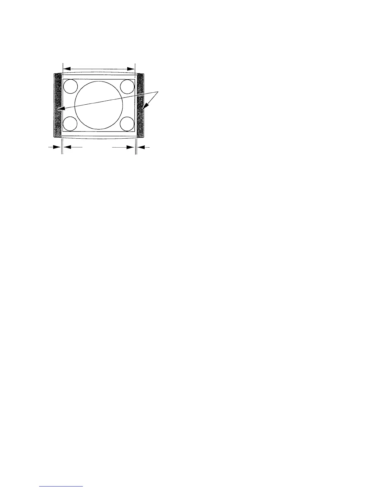
4. Adjust the H. BLK. LEFT data so that the blanking is
position at 7 mm outside the left-most end of the cross-
hatch signal area. (Fig. 1-7.)
When this adjustment is complete, take note of the H.
BLK. LEFT adjustment data.
5. Adjust the H. BLK. RIGHT data so that the blanking is
position at 7 mm outside the right-most end of the
cross-hatch signal area. (Fig. 1-7.)
When this adjustment is complete, take note of the H.
BLK. RIGHT adjustment data.
6. H CENTER
H PHASE
H BLK LEFT
H BLK RIGHT
Copy the above-described data to the following modes.
MODE8/MODE12 525 16:9 UNDER SCAN
MODE9/MODE13 4:3 NORMAL
MODE10/MODE14 4:3 UNDER SCAN
. 1080/48i (27 kHz) 16:9 NORMAL mode horizontal
blanking adjustment
1. Select 1080 16:9 NORM of the SCREEN mode using the
INPUT CONFIGURATION menu of the SETUP menu.
2. Connect the MODE15 1080/48i (27 kHz) cross-hatch
signal to the input.
3. Adjust the H. CENTER, H. PHASE, H. BLK. LEFT and H.
BLK. RIGHT data in the same manner as steps 3 to 12 of
the 1080/60i (33 kHz) 16:9 NORMAL mode.
4. Adjust the H. BLK. LEFT data so that the blanking is
position at 7 mm outside the left-most end of the cross-
hatch signal area. (Fig. 1-7.)
When this adjustment is complete, take note of the H.
BLK. LEFT adjustment data.
5. Adjust the H. BLK. RIGHT data so that the blanking is
position at 7 mm outside the right-most end of the
cross-hatch signal area. (Fig. 1-7.)
When this adjustment is complete, take note of the H.
BLK. RIGHT adjustment data.
6. H CENTER
H PHASE
H BLK LEFT
H BLK RIGHT
Copy the above-described data to the following modes.
MODE16 1125 16:9 UNDER SCAN
Fig. 1-7
13. H CENTER
H PHASE
H BLK PHASE
H BLK WIDTH
Copy the above data to the following mode.
MODE2 1125 16:9 UNDER SCAN
MODE3 1035/60i (33kHz) 16:9 NORMAL
MODE4 1125 (1035) 16:9 UNDER SCAN
• 720/60P (45 kHz) 16:9 NORMAL Mode H Blanking
Adjustment
1. Set SCREEN MODE to 720P 16:9 NORM at the
INPUT CONFIGURATION menu of the SETUP
menu.
2. Connect the MODE5 720/60P (45 kHz) cross-hatch
signal to the input.
3. Adjust the H. CENTER, H. PHASE, H. BLK. LEFT
and H. BLK. RIGHT data in the same manner as steps
3 to 12 in the 1080/60i (33 kHz) 16:9 NORMAL
mode.
4. Adjust the H. BLK. LEFT data so that the blanking is
position at 7 mm outside the left-most end of the cross-
hatch signal area. (Fig. 1-7.)
5. Adjust the H. BLK. RIGHT data so that the blanking is
position at 7 mm outside the right-most end of the
cross-hatch signal area. (Fig. 1-7.)
6. H CENTER
H PHASE
H BLK LEFT
H BLK RIGHT
Copy the above data to the following mode.
MODE6 16:9 UNDER SCAN
H BLK
Signal area
3~7mm
H BLK LEFT H BLK RIGHT
 Loading...


