58 (E)
Chapter 3 Appendix
A1
AA2
B
C(1/2)
C(2/2)
B1(1/2)
B2
B3
B21
C1
C2
B1(2/2)
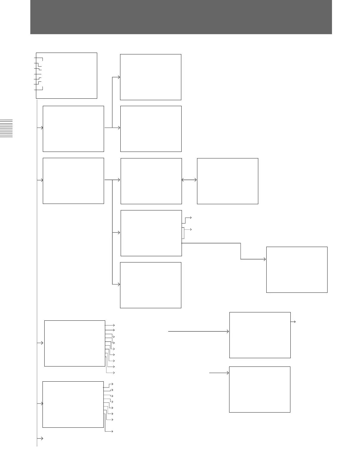
MAIN MENU
Set by automatic adjustment (using the
color bar signal)
Set input signal data for each channel.
:Current channel is indicated.
:Select the input signal type.
:Select the slot number.
:Select the input connector number.
:Select the slot when the external sync signal is used.
:Select the audio input number (BVM-D9H5 only)
:Select the color temperature.
:Enter the aperture adjustment value.
:Give the channel name. (Select in the “C2” menu)
Set the preset value with the
adjustment knobs.
D (next page)
:Select the level of
YP
BPR signals.
:Current channel is indicated.
:Select the number of active scanning lines per frame.
:Set the holizontal picture position.
:Set the 4:3 marker position.
:Set the 4:3 marker width.
:Set the NTSC setup level when the BKM-127W is installed.
:Select the matrix when YP
BPR signals of the signal formats
480/60I or 480/60P are input.
:Select ON to compensate for a distorted picture when the input
signals from the VCR are not typical. (Effective only when the
signal formats 480/60I or 575/50I are input.)
You can copy the color temperature
data.
Menu Configuration
CONTROL PRESET ADJ...
MENU
COLOR TEMP ADJ...
INPUT CONFIG...
REMOTE...
SYSTEM CONFIG...
STATUS...
ALIGNMENT...
p
A
B
C
D
E
F
G
CHROMA:100CONTRAST:100
PHASE :100BRIGHT :100
MANUAL
TO CANCEL :MENU KEY
TO CONFIRM:ENTER KEY
MANUAL...
CONTROL PRESET ADJ
AUTO...
p
AUTO
FULL FIELD WHITE 100%
8COLOR BAR 100%
8COLOR BAR 75%
SMPTE OLOR BAR
EIA COLOR BAR
C
p
STD
COLOR TEMP ADJ
MANUAL
PROBE...
COPY...
p
TS D
ADJUST
↓
RED:CONTRAST KNOB
GREEN :BRIGHT KNOB
BLUE :CHROMA KNOB
LUMINANCE :PHASE KNOB
TO CANCEL :MENU KEY
TO CONFIRM :ENTER KEY
↓
AIN
:0500 G:0500 R:0500
G
B
TS D
ADJUST
↓
↓
IAS
:0500 G:0500 R:0500
B
B
STD
PROBE
START
PROBEBKM-14L
X0.313
Y 0.329
LOWLIG T ( 20IRE) 2.7
HIGHLIGHT(100IRE) 120
LOADREFVALUE...
H
p
STD
COPY FROM
STD
COL1
COL2
D65
D93
p
REF VALUE
D65
D93
p
HC 1
FORMAT
YPBPRSMPTE
RGB
NTSC,PAL
D1-SDI
HD-SDI
p
HC 1
CHANNEL NAME
PROG
EDIT
CAM
VTR
NEW NAME
p
HC 1
INPUT CONFIG(1/2)
↓
FORMAT... YPBPR
SLOTNOSLOT1
INPUTNO1
EXT SYNC SLOT SLOT1
AUDIO INPUT 1
COLOR TEMP STD
APERTURE VALUE 100
CHANNEL NAME... PROG
p
↓
HC 1
INPUT CONFIG(2/2)
↓
1125/60I SYSTEM 1080I
HPHASE000
MARKER PHASE 000
MARKER WIDTH 000
NTSC SETUP 7.5
YPBPR MATRIX 60I
VCR MODE OFF
p
↓
Select the probe for color temperature adjustment.
:Select the probe (BKM-14L, SLS 9400, CA-100, TF6,
or PM 5639)
:Confirm/Change x, y value on the Chromaticity
Coordinate and luminance