5-30
PD-131 board
1-6. LCD SYSTEM ADJUSTMENT
(CCD-TRV49/TRV49E/TRV58/TRV58E/TRV59E/
TRV68/TRV78/TRV78E/TRV88/TRV98/TRV98E)
Note 1: The back light (fluorescent tube) is driven by a high voltage AC
power supply. Therefore, do not touch the back light holder to
avoid electrical shock.
Note 2: When replacing the LCD unit, be careful to prevent damages
caused by static electricity.
Note 3: Set the LCD BRIGHT (Menu display) to the center.
Set the LCD COLOR (Menu display) to the center.
Note 4: Connect the adjustment remote commander to CN713 of VC-251
board or CPC connector of FP-262 flexible via CPC jig for BX/
BK (J-6082-521-A). To operate the adjustment remote commander,
connect the AC power adapter (8.4Vdc) to the DC IN jack of CPC
jig for BX/BK, or connect the L series Info-LITHIUM battery to
the battery terminal of CPC jig for BX/BK.
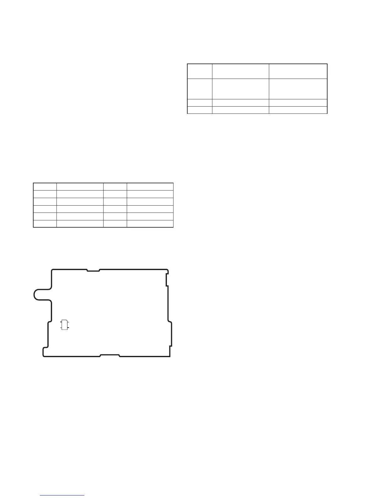
[Adjusting connector]
Most of the measuring points for adjusting the LCD system are
concentrated in CN5502 of the PD-131 board. Connect the
measuring instruments via the multi CPC jig (J-6082-311-A). The
following table shows the Pin No. and signal name of CN5502.
1. LCD Type Check
By measuring the resistor value between Pin 6 of CN5502 and
GND, the type of LCD can be discriminated.
Table. 5-1-8.
Pin No.
1
3
5
7
9
Signal Name
VB
VG
VR
C-SYNC/XHD
GND
Pin No.
2
4
6
8
10
Signal Name
XVD OUT
PANEL COM/PSIG
PANEL ID
XHD OUT
GND
Resistor
value
1.0kΩ
4.7kΩ
5.6kΩ
Table. 5-1-9.
LCD type
2.5 LCD TYPE S (61k)
3.0 LCD TYPE S (123k)
3.5 LCD TYPE S (123k)
CCD-
TRV49,TRV49E,TRV58,
TRV58E,TRV59E,
TRV68,TRV78,TRV78E
TRV88
TRV98,TRV98E
12
10 9
CN5502