5-45
A
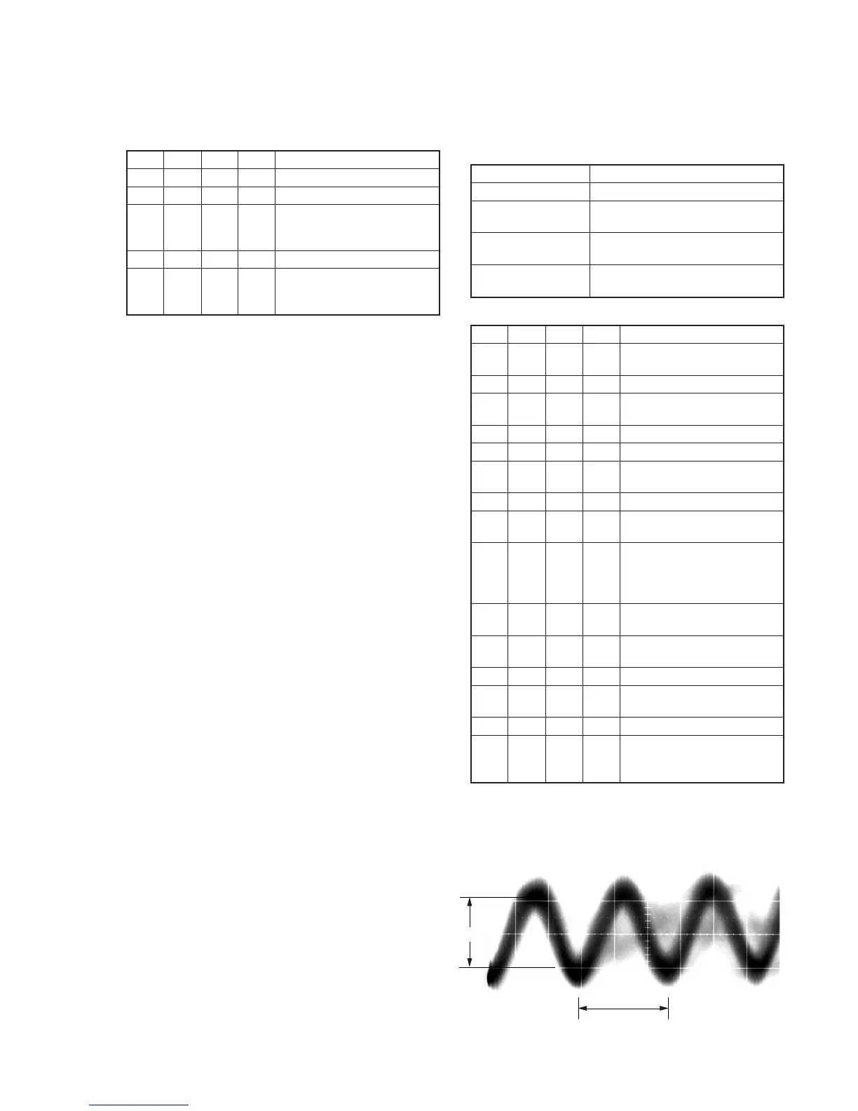
1.35
µ
sec
Center of the luminance line width
Fig. 5-3-10.
7. REC C/AFM Current Adjustment
7-1. Preparations
Order Page
Address
Data Procedure
1 0 01 01 Set the data.
2 D 14 Write down the data.
3 D 14 Set the following data, and press
PAUSE button.
06 (NTSC), 26 (PAL)
4 D 15 Write down the data.
5 D 15 Set the following data, and press
PAUSE button.
6D (NTSC), 6F (PAL)
Note: Don’t disconnect the DC power supply of the camcorder during the
following adjustments.
When the following symptom occurs, reset the data of D page to the
values written down.
1) The power is shut off so that unit cannot operate.
7-2. REC C Current Check (VC-251 board)
Check the recording current level of the REC Chroma signal. If it is
too low, chroma signal noise in played back picture will be increased.
If too high, Y signal noises will increase and white modulation noises
will be produced.
Mode VTR recording (SP mode)
Signal No signal
Measurement Point REC RF (Pin qg of CN713 or Pin qg
of CPC connector of FP-262 flexible)
Measuring Instrument Oscilloscope
(20 MHz BW LIMIT: OFF)
Specified Value A=50.8 ± 3.0mV (NTSC)
A=54.0 ± 3.0mV (PAL)
Adjusting method:
Order Page
Address
Data Procedure
1 Insert a Hi8 ME tape, and set to
VTR recording mode. (Note)
2 0 01 01 Set the data.
3 2 01 41 Set the data, and press PAUSE
button.
4 6 61 30 Set the data.
5 E FB Write down the data.
6 E FB 05 Set the data, and press PAUSE
button.
7 F 71 Write down the data.
8 F 71 00 Set the data, and press PAUSE
button.
9 Check that the REC chroma
signal level (A) satisfies the
specified value, and write down
the signal level.
10 F 71 Set the data written down at step
7, and press PAUSE button.
11 E FB Set the data written down at step
5, and press PAUSE button.
12 6 61 10 Set the data.
13 2 01 00 Set the data, and press PAUSE
button.
14 0 01 00 Set the data.
15 Perform “REC AFM Current
Adjustment” and “Processing
after completed adjustment”.
Note: Use the REC buttons of the adjustment remote commander (with
the HOLD switch set in the OFF position).