28
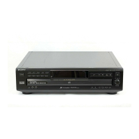
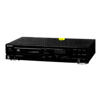
CDP-CE275/CE375
• MAIN BOARD IC301 CXP82532-013Q
(SYSTEM CONTROLLER, FLUORESCENT INDICATOR TUBE DRIVER, KEY CONTROL)
Pin No. Pin Name I/O Description
1 BUSIN I Sircs remote control signal input terminal Not used (pull up)
2 RMIN I Remote control signal input from the remote control receiver (IC802)
3 NC I Not used (open)
4 XLT O Serial data latch pulse signal output to the CXD2587Q (IC101)
5 LDON O Laser diode ON/OFF output
6 TSENS I/O Detect signal input from the table sensor (D10)
7 DA CS I/O DA CS
8 CLK I/O Serial data transfer clock signal output to the CXD2587Q (IC101)
9 LDON/RW I/O Laser diode ON/OFF output
10 DATA I/O Serial data output to the CXD2587Q (IC101)
11 SQCK I/O Sub-code Q data reading clock signal output to the CXD2587Q (IC101)
12 SUBQ I/O Sub-code Q data signal input from the CXD2587Q (IC101)
13 NC O Not used (open)
14 OUT SW I/O Detect signal input from the open/close detect switch (S11)
15 S1 I/O Detect signal input from the tray address detect switch (S200)
16 S2 I/O Detect signal input from the tray address detect switch (S200)
17 NC I/O Not used (open)
18 TBLL I/O Table motor drive signal (counterclockwise) output to the BA6780 (IC11)
19 TBLR I/O Table motor drive signal (clockwise) output to the BA6780 (IC11)
20 LD IN I/O Loading motor (M11) drive signal output to the BA6780 (IC11) *1
21 LD OUT I/O Loading motor (M11) drive signal output to the BA6780 (IC11) *1
22 NC I/O Not used (open)
23 NC I/O Not used (open)
24 TEST I/O Key input terminal (A/D input)
25 KEY3 I/O Key input terminal (A/D input) (S812 to S816)
26 KEY4 I/O Key input terminal (A/D input) (S817 to S821)
27 KEY5 I/O Key input terminal (A/D input) (S806 to S810)
28 KEY6 I/O Key input terminal (A/D input) (S801 to S805)
29 NC I/O Not used (open)
30 RST I/O
System reset signal input from the reset signal generator (IC601) “L”:reset
For several hundreds msec. after the power supply rises, “L” is input, then it changes to “H”
31 EXTAL I Main system clock input terminal (10 MHz)
32 XTAL O Main system clock output terminal (10 MHz)
33 VSS — Ground terminal
34 NC O Not used (open)
35 NC O Not used (open)
36 NC O Not used (open)
37 NC O Not used (open)
*1 Loading motor (M11) control
Operation
OFF OFF IN BRAKE
Terminal
LOAD IN (pin @º) “L” “L” “H” “H”
LOAD OUT (pin @¡) “L” “H” “L” “H”