Cautions
l
This unit is designed for negative ground 12 V
DC operation only
l
Do not get the wires under a screw, or caught
in moving parts (e g seat railing)
l
Before making connections, disconnect the
ground terminal of the car battery to avoid
short circuits
l
Connect the yellow and
red
power input leads
only after all other leads have been connected
l
Run all ground wires to a common ground
point
l
Be sure to insulate any loose unconnected
wires with electrical tape for safety
Notes on the power supply cord (yellow)
l
When connecting this unit in combination with
other stereo components, the connected car
circuit’s rating must be higher than the sum of
each component’s fuse
l
When no car circuits are rated high enough,
connect the unit directly to the battery
Connection example (m)
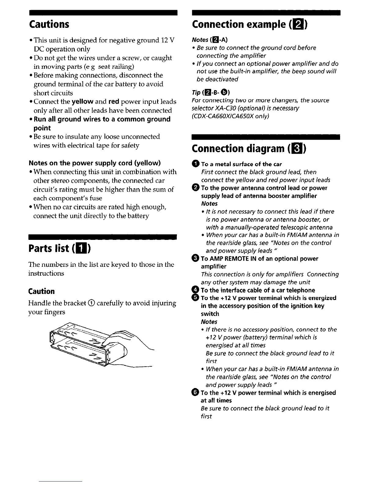
Parts list (0)
The numbers in the list are keyed to those in the
instructions
Caution
Handle the bracket @ carefully to avoid injuring
your fingers
Notes (@A)
l
Be sure to connect the ground cord before
connecting the amplifier
l
If you connect an optional power amplifier and do
not use the built-in amplifier, the beep sound will
be deactivated
rip (O-B- 0,
For connecting two or more changers, the source
selector XA-C30 (optional) is necessary
(CDX-CA66OXICA65OX on/y)
Connection diagram (a)
@To a metal surface of the car
First connect the black ground lead, then
connect the yellow and red power input leads
0 To the power antenna control lead or power
supply lead of antenna booster amplifier
Notes
l
It is not necessary to connect this lead if there
is no power antenna or antenna booster, or
with a manual/y-operated telescopic antenna
l
When your car has a built-in FMIAM antenna in
the rear/side glass, see “Notes on the control
and power supply leads U
0 To AMP REMOTE IN of an optional power
amplifier
This connection is on/y for amplifiers Connecting
’
8
any other system may damage the unit
To the interface cable of a car telephone
To the +12 V power terminal which is energized
in the accessory position of the ignition key
switch
Notes
l
If there is no accessory position, connect to the
+I2 Vpower (battery) terminal which is
energised at a// times
Be sure to connect the black ground lead to it
first
l
When your car has a built-in FM/AM antenna in
the rear/side glass, see “Notes on the control
and power supply leads I
0 To the +12 V power terminal which is energised
at all times
Be sure
to
connect the black ground lead to it
first
 Loading...