35
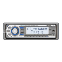
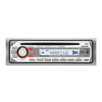
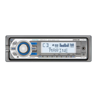
CDX-M50IP/MR50IP
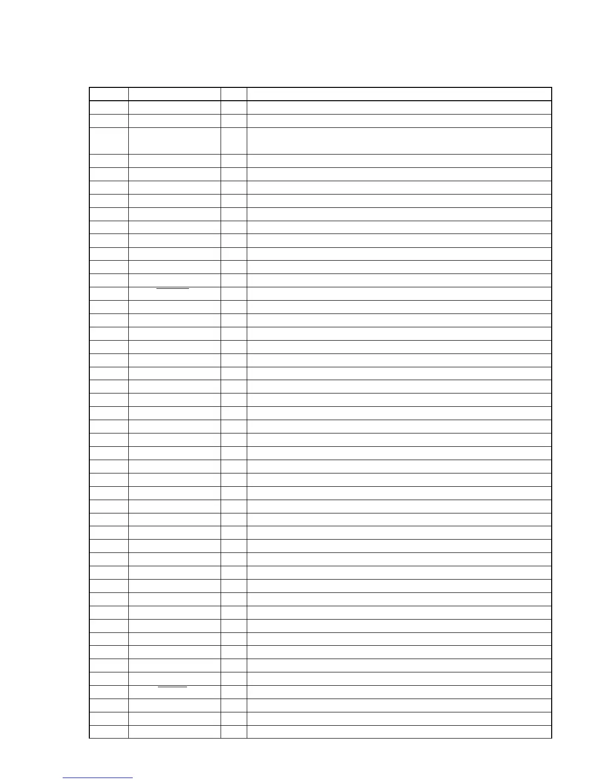
• IC Pin Description
IC501 MB90F045PF-G-9061-SPE1 (SYSTEM CONTROL) (MAIN BOARD (4/4))
Pin No. Pin Name I/O Pin Description
1 AREASEL0 I Destination setting pin (L: CDX-M50IP, H: CDX-MR50IP)
2 AREASEL1 I Destination setting pin (Fixed at L in this set)
3 AREASEL2 I
Destination setting pin (L: FM (200k)/AM (10k), H: FM (50k)/AM (9k)
(CDX-M50IP only))
4 AREASEL3 I Destination setting pin (L: CDX-MR50IP, H: CDX-M50IP)
5 BEEP O Beep signal output to power amp IC.
6 AMPSTB O Standby signal output to power amp IC.
7 DIAG I Status signal input from power amp IC.
8 NCO O Not used. (Open)
9 SA_DATA O Data output for electronic volume IC spectrum analyzer.
10 SA_CKO O Spectrum analyzer clock signal output
11 VSS — Ground
12 TUATT O Tuner mute control signal output
13 NSMASK O Noise mask signal output (CDX-MR50IP only)
14 VOLATT O Attenuator control signal output to electronic volume IC.
15 ILLUMI_SEL I Illumination voltage setting pin (L: illumination power supply 9 V)
16 to 20 NCO O Not used. (Open)
21 B-OUT_SEL I Black out select signal input (L: non black out)
22 NCO O Not used. (Open)
23 VCC5 — Power supply pin (+3.3 V)
24 EEP_SIO I/O Serial data signal input/output for EEPROM communication.
25 EEP_CKO O Serial clock signal output for EEPROM communication.
26 RDS_ON O RDS ON signal output (CDX-MR50IP only)
27 LCD_CE O Chip enable signal output to LCD drive IC.
28 LCD_SO O Serial data signal output to LCD drive IC.
29 LCD_SCK O Serial clock signal output to LCD drive IC.
30 DOOR_IND O DISC IN indicator LED control signal output
31 RE_IN0 I Rotary encoder signal input 0
32 RE_IN1 I Rotary encoder signal input 1
33 I2C_SCK O I2C bus serial clock signal output
34 I2C_SIO I/O I2C bus serial data signal input/output
35 DAVDD — Power supply pin for A/D converter. (+3.3 V)
36 AVRH — External reference power supply pin for A/D converter. (+3.3 V)
37 DAVSS — Ground for A/D converter.
38 QUALITY I Noise detection signal input (CDX-MR50IP only)
39 VSM I S meter voltage detection signal input
40 KEYIN1 I Key signal input 1
41 KEYIN0 I Key signal input 0
42 VSS — Ground
43 RC_IN0 I Rotary commander key signal input
44 INI_COL I Initial color setting signal input (L: red)
45 COL_SEL I Key illumination 2 colors select signal input (H: 2 color)
46 SA_IN I Spectrum analyzer signal input
47 NCO O Not used. (Open)
48 AD_ON O A/D converter power supply control signal output
49, 50 MD0, MD1 I Signal input for operation mode designation. (Fixed at H in this set)
51 MD2 I Signal input for operation mode designation. (Fixed at L in this set)
52 KEYACK I Key acknowledge detection signal input