Do you have a question about the Sony CDX-M50IP and is the answer not in the manual?
Details the minimum continuous average power output and total harmonic distortion for the US model.
Provides specifications for the CD player, including signal-to-noise ratio and frequency response.
Lists tuning ranges and intermediate frequencies for the FM tuner.
Details the tuning range and interval for the AM band on the CDX-M50IP model.
Precautions for preventing electrostatic breakdown when handling the optical pick-up block.
Guidelines for safely checking the laser diode emission from the optical pick-up.
Warning regarding the use of controls and procedures other than specified.
Indicates the product is classified as a Class 1 Laser product with label location.
Notes on reusing or handling chip components and tantalum capacitors.
Lists specific test discs recommended for checking the CD section.
Information on compatible CD disc types and playback formats.
Instructions for connecting an extension cable for servicing the set.
Notes regarding the replacement of the Servo Board and AUX Jack.
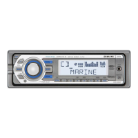
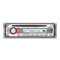
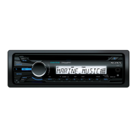
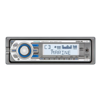
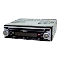
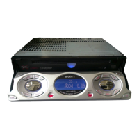
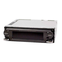
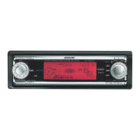
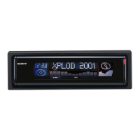
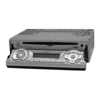
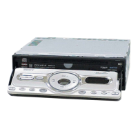
Identifies controls on the main unit and card remote commander.
Diagrams illustrating connection terminals for the CDX-M50IP model.
Diagrams illustrating connection terminals for the CDX-MR50IP model.
Disassembly step for the SUB (AUX) PANEL ASSEMBLY.
Disassembly step for the CD MECHANISM BLOCK.
Disassembly step for the MAIN BOARD.
Disassembly step for the SERVO BOARD.
Disassembly step for the CHASSIS (T) SUB ASSY.
Disassembly step for the ROLLER ARM ASSY.
Disassembly step for the CHASSIS (OP) ASSY.
Disassembly step for the CHUCKING ARM SUB ASSY.
Disassembly step for the SLED MOTOR ASSY.
Disassembly step for the OPTICAL PICK-UP SECTION.
Disassembly step for the OPTICAL PICK-UP.
Explains the purpose and basic operation of the diagnostics function.
Procedure for exiting the diagnostics function mode.
Describes the initial display and how to navigate diagnosis modes.
Details the information displayed in various diagnostic modes.
Explains how to display the operating hours of the unit.
Details how to display CD error information and its history.
Provides a table of error codes and their descriptions for CD errors.
Shows disc type indications and associated operating hours.
Explains how to display offset/failure error information and its history.
Common notes for printed wiring boards and schematic diagrams.
Presents waveform examples for the MAIN and iPod boards.
Shows the system block diagram for the main section of the unit.
Shows the system block diagram for the display section of the unit.
Illustrates the layout of components on the main section's printed wiring board.
Presents the first part of the main section schematic diagram.
Presents the second part of the main section schematic diagram.
Presents the third part of the main section schematic diagram.
Presents the fourth part of the main section schematic diagram.
Illustrates the component layout for the iPod section's printed wiring board.
Provides the schematic diagram for the iPod section.
Illustrates the component layout for the sub section's printed wiring board.
Provides the schematic diagram for the sub section.
Illustrates the component layout for the display section's printed wiring board.
Provides the schematic diagram for the display section.
Block diagram for IC300, a power amplifier and voltage regulator.
Block diagram for IC601, a bus interface controller.
Block diagram for IC401, an electronic volume control IC.
Block diagram for IC50, a tuner IC for the CDX-MR50IP.
Block diagram for IC800, an iPod charge control IC.
Block diagram for IC250, the microcontroller for iPod control.
Detailed pin description for the system control IC501.
Exploded view illustrating the main section components and assembly.
Exploded view illustrating the front panel components and assembly.
Exploded view illustrating the CD mechanism components and assembly.
List of electrical parts for the iPod board.
List of electrical parts for the Key board.
List of electrical parts for key components like diodes, resistors, transistors.
List of electrical parts for the Main board, covering resistors and capacitors.
List of electrical parts for the Main board, covering capacitors and diodes.
List of electrical parts for the Main board, covering diodes, ICs, and jacks.
List of electrical parts for the Main board, covering transistors and resistors.
List of electrical parts for the Main board, covering resistors, switches, tuner, and vibrator.
List of parts for the Servo board, Sub board, and connections.
Records the revision history of the service manual.
| Brand | Sony |
|---|---|
| Model | CDX-M50IP |
| Category | Car Receiver |
| Language | English |