4
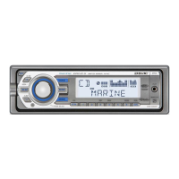
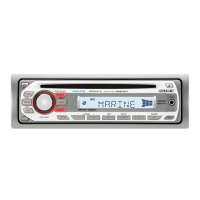
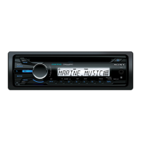
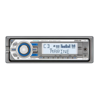
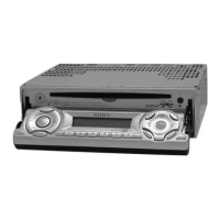
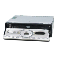
CDX-M50IP/MR50IP
TABLE OF CONTENTS
1. SERVICE NOTE ........................................................ 5
2. GENERAL
Location of controls and basic operations ....................... 6
Connections (CDX-M50IP) ............................................ 6
Connections (CDX-MR50IP) .......................................... 8
3. DISASSEMBLY
3-1. Sub (AUX) Panel Assy .................................................... 11
3-2. CD Mechanism Block ..................................................... 11
3-3. MAIN Board.................................................................... 12
3-4. SERVO Board.................................................................. 12
3-5. Chassis (T) Sub Assy....................................................... 13
3-6. Roller Arm Assy .............................................................. 13
3-7. Chassis (OP) Assy ........................................................... 14
3-8. Chucking Arm Sub Assy ................................................. 14
3-9. Sled Motor Assy .............................................................. 15
3-10. Optical Pick-up Section ................................................... 16
3-11. Optical Pick-up ................................................................ 16
4. DIAGNOSIS FUNCTION ........................................ 17
5. DIAGRAMS
5-1. Block Diagram –Main Section– ...................................... 21
5-2. Block Diagram –Display Section– .................................. 22
5-3. Printed Wiring Board –Main Section– ............................ 23
5-4. Schematic Diagram –Main Section (1/4)– ...................... 24
5-5. Schematic Diagram –Main Section (2/4)– ...................... 25
5-6. Schematic Diagram –Main Section (3/4)– ...................... 26
5-7. Schematic Diagram –Main Section (4/4)– ...................... 27
5-8. Printed Wiring Board –iPod Section– ............................. 28
5-9. Schematic Diagram –iPod Section– ................................ 28
5-10. Printed Wiring Board –Sub Section– .............................. 29
5-11. Schematic Diagram –Sub Section– ................................. 29
5-12. Printed Wiring Board –Display Section– ........................ 30
5-13. Schematic Diagram –Display Section– ........................... 31
6. EXPLODED VIEWS
6-1. Main Section.................................................................... 37
6-2. Front Panel Section ......................................................... 38
6-3. CD Mechanism Section (MG-101FC-188//Q) ................ 39
7. ELECTRICAL PARTS LIST .................................. 40