41
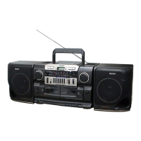
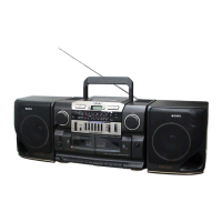
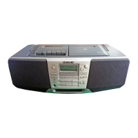
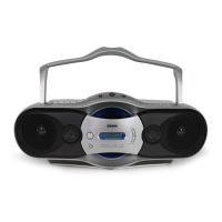
CFD-CD777SMK2
7-1. REAR CABINET SECTION
SECTION 7
EXPLODED VIEWS
The components identified by
mark 0 or dotted line with mark
0 are critical for safety.
Replace only with part number
specified.
• Items marked “*” are not stocked since they
are seldom required for routine service. Some
delay should be anticipated when ordering
these items.
• Accessories are given in the last of the elec-
trical parts list.
NOTE:
• -XX and -X mean standardized parts, so they
may have some difference from the original
one.
• Color Indication of Appearance Parts
Example:
KNOB, BALANCE (WHITE) . . . (RED)
↑↑
Parts Color Cabinet's Color
Ref. No. Part No. Description Remark
Ref. No. Part No. Description Remark
* 1 A-3321-711-A AMP BOARD, COMPLETE
* 2 1-670-300-11 BATTERY BOARD
3 3-028-480-01 SPRING (+), BATTERY
4 3-028-481-01 SPRING (–), BATTERY
* 5 1-670-306-11 SPEAKER BOARD
6 3-022-861-21 CABINET, REAR
7 3-028-479-01 SPRING (+. –), BATTERY
8 3-022-870-01 HANDLE
9 3-389-436-11 LID, BATTERY CASE
10 3-022-875-01 TERMINAL, ANTENNA
* 11 1-670-303-11 POWER BOARD
12 3-261-339-01 CHASISS DC JACK
13 4-951-620-01 SCREW (2.6X8), +BVTP
* 14 1-860-815-11 DC JACK BOARD
ANT1 1-501-900-21 ANTENNA, TELESCOPIC (FM/SW)
0F903 1-533-473-12 FUSE, GLASS TUBE (DIA. 5) (6.3A/250V)
0T901 1-431-938-21 TRANSFORMER, POWER
#1 7-685-647-79 SCREW +BVTP 3X10 TYPE2 N-S
#2 7-685-651-79 SCREW +BVTP 3X20 TYPE2 N-S
#3 7-682-548-09 SCREW +B 3X8