2
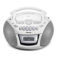
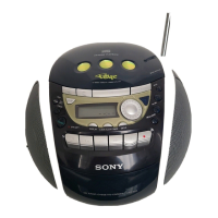
CFD-E77L
TABLE OF CONTENTS
1. SERVICING NOTES.............................................. 3
2. GENERAL .................................................................. 4
3. DISASSEMBLY
3-1. Disassembly Flow ........................................................... 7
3-2. Cabinet Lower Assy ........................................................ 8
3-3. AC INLET Board, Power Board..................................... 8
3-4. TUNER Board, MAIN Board ......................................... 9
3-5. Cover Plate Assy ............................................................. 9
3-6. CD Mechanism Deck (KSM-213CDP) .......................... 10
3-7. Optical Pick-up (KSS-213C) .......................................... 10
3-8. Cabinet Front Assy.......................................................... 11
3-9. Tape Mechanism Deck (MF-V5-117) ............................ 11
3-10. CD Lid ............................................................................. 12
3-11. Lid Cassette Assy, LCD Board ....................................... 12
3-12. Head (HRP301), Motor Assy (M301), Belt ................... 13
3-13. Connector Setting............................................................ 13
4. MECHANICAL ADJUSTMENTS ...................... 14
5. ELECTRICAL ADJUSTMENTS
Tape Deck Section ......................................................... 14
Tuner Section ................................................................. 15
CD Section ..................................................................... 17
6. DIAGRAMS
6-1. Block Diagram – CD Section – .................................... 19
6-2 Block Diagram – TUNER Section – ............................ 20
6-3. Block Diagram – MAIN Section – ............................... 21
6-4. Block Diagram – POWER SUPPLY Section – ............ 22
6-5. Note for Printed Wiring Boards and
Schematic Diagrams ....................................................... 23
6-6. Printed Wiring Board – CD Section – .......................... 24
6-7. Schematic Diagram – CD Section – ............................. 25
6-8. Printed Wiring Board – TUNER Section – .................. 26
6-9. Schematic Diagram – TUNER Section – ..................... 27
6-10. Printed Wiring Board – TAPE DECK Section – .......... 28
6-11. Schematic Diagram – TAPE DECK Section – ............. 28
6-12. Printed Wiring Boards – MAIN/LCD Boards –........... 29
6-13. Schematic Diagram – MAIN Board (1/2) – ................. 30
6-14. Schematic Diagram – MAIN (2/2)/LCD Boards – ...... 31
6-15. Printed Wiring Boards – PANEL Section – ................. 32
6-16. Schematic Diagram – PANEL Section – ...................... 33
6-17. Printed Wiring Boards
– POWER SUPPLY Section – ....................................... 34
6-18. Schematic Diagram
– POWER SUPPLY Section – ....................................... 35
6-19. IC Pin Function Description .......................................... 39
7. EXPLODED VIEWS
7-1. Cabinet Section ............................................................... 41
7-2. Cabinet Upper Section .................................................... 42
7-3. Cabinet Front Section ..................................................... 43
7-4. Cabinet Lower Section.................................................... 44
7-5. Optical Pick-up Section (KSM-213CDP) ...................... 45
7-6. Tape Mechanism Deck Section-1 (MF-V5-117) ............ 46
7-7. Tape Mechanism Deck Section-2 (MF-V5-117) ............ 47
8. ELECTRICAL PARTS LIST .............................. 48
SAFETY-RELATED COMPONENT WARNING!!
COMPONENTS IDENTIFIED BY MARK 0 OR DOTTED
LINE WITH MARK 0 ON THE SCHEMATIC DIAGRAMS
AND IN THE PARTS LIST ARE CRITICAL TO SAFE
OPERATION. REPLACE THESE COMPONENTS WITH
SONY PARTS WHOSE PART NUMBERS APPEAR AS
SHOWN IN THIS MANUAL OR IN SUPPLEMENTS PUB-
LISHED BY SONY.
Notes on chip component replacement
• Never reuse a disconnected chip component.
• Notice that the minus side of a tantalum capacitor may be dam-
aged by heat.
CAUTION
Use of controls or adjustments or performance of procedures
other than those specified herein may result in hazardous ra-
diation exposure.
This Compact Disc player is classified as a
CLASS 1 LASER product.
The CLASS 1 LASER PRODUCT label is located
at the rear.
w
w
w
.
x
i
a
o
y
u
1
6
3
.
c
o
m
Q
Q
3
7
6
3
1
5
1
5
0
9
9
2
8
9
4
2
9
8
T
E
L
1
3
9
4
2
2
9
6
5
1
3
9
9
2
8
9
4
2
9
8
0
5
1
5
1
3
6
7
3
Q
Q
TEL 13942296513 QQ 376315150 892498299
TEL 13942296513 QQ 376315150 892498299
http://www.xiaoyu163.com
http://www.xiaoyu163.com