EasyManua.ls Logo

Sony CHC-P11 User Manual

Sony CHC-P11
64 pages
To Next Page IconTo Next Page
Page #1 background imageLoading...
Page #1 background image
CHC-P11/P11!
SERVICE
MANUAL
*
CHC-P11/P11J
are
composed
of
following
models.
AEP
Model
UK
Model
E
Model
Australian
Model
CHC-PI11
As
for
the
service
manual,
it is
issued
for
each
component
model,
then,
please
refer
to
it.
Saudi
Arabia
Model
CHC-P11J
COMPONENTS
MODEL
NAME
FOR
THIS
SYSTEM
TUNER
/
CD
PLAYER
/
SPEAKER
i
i
i
TAPE
DECK
/
AMPLIFIER
oor
LIST
(Accessories
&
Packing
Materials)
CHC-P11
HCD-H11
eens
e
ltems
marked
*”
are
not
stocked
since
they
are
as
seldom
required
for
routine
service.
Some
delay
CHC-P11J
HCD-H11J
should
be
anticipated
when
ordering
these
items.
No.
Part
No.
Description
Remark
SPECIFICATIONS
a
oe
=—_—
G
1-473-397-21
COMMANDER,
STANDARD
(RM-S11)
SUeta
1-501-594-11
ANTENNA,
FM
(AEP,UK,G,IT,EE,AED)
Power
requirements
1-501-695-11
ANTENNA,
FM
(EXCEPT
AEP,UK,G,IT,EE,AED)
Australian
model
:
240V
AC,
50/60Hz
1-501-721-11
ANTENNA,
LOOP
AEP,
German,
italian,
East
European
model:
3-800-628-11
MANUAL,
INSTRUCTION
(ENGLISH)
(UK)
ie
Reale
oe
poe
3-800-628-21
MANUAL,
INSTRUCTION
ERE
east
4
(ENGLISH,
FRENCH,SPANISH
PORTUGUESE)
(AEP)
110
-
120V
or
220~
240V
AC,
50/60Hz
3-800-628-31
MANUAL,
INSTRUCTION
(GERMAN,
DUTCH,
ITALIAN)
(AEP,
IT}
Adjustable
with
the
voltage
selector
3-800-628-41
MANUAL,
INSTRUCTION
(GERMAN)
(G)
Power
consumption
3-800-628-51
MANUAL,
INSTRUCTION
(DANISH,FRENCH,(TALIAN
SWEDISH)
(AED)
75W
3-800-628-61
MANUAL,
INSTRUCTION
,
:
(ENGLISH,
FRENCH,
SPANISH,
CHINESE)
Dimensions
(E,MX,MY,SP,
TW,HK,AR,AUS,
CHC-P11
:
EA)
Approx.
225X210
235mm
(w/h/d)
incl.
projecting
parts
and
controls
3-800-628-71
MANUAL,
INSTRUCTION
(ARABIC)
(CHC-P11
:
EA,
E3,
TW)
Mass
3-800-628-91
MANUAL,
INSTRUCTION
(ENGLISH,
POLISH,
RUSSIAN)
(EE)
3-810-721-12
MANUAL,
INSTRUCTION
=
Papieks
tere
(ENGLISH,
FRENCH,
SPANISH,
CHINESE)
(CHC-P11J)
Supplied
accessories
3-810-721-22
MANUAL,
INSTRUCTION
(ARABIC)
(CHC-PitJ)
AM
loop
antenna
(1)
4-981-537-01
COVER,
BATTERY
(for
RM-S11)
Remote
(1)
Sany
SUNS
(NS)
bra
(2)
Pee
cicada
*
i. ce
=
a
"
ee,
*
4-980-072-02
INDIVIDUAL
CARTON
(AEP.UK,G,IT,EE,AED)
a
*
4-980-073-02
INDIVIDUAL
CARTON
(E,MX,MY,SP,HK,AR)
Design
and
specifications
are
subject
to
change
without
notice.
|
«
4-980-073-12
INDIVIDUAL
CARTON
(TW,
CHC-P11:
EA)
@
Abbreviations
*
4-980-138-02
INDIVIDUAL
CARTON
(AUS)
AUS:
Australian
HK
:
Hong
Kong
*
4-980-347-01
INDIVIDUAL
CARTON
(CHC-P11J)
AR
:
Argentine
G
=:
German
*
4-980-075-01
CUSHION
(SS)
(CHC-P1i1)
MX
:
Mexican
IT:
Itafian
*
4-977-416-01
CUSHION
(SS)
(CHC-P11J)
MY
:
Malaysia
EE
:
East
European
SP
:
Singapore
TW
:
Taiwan
be
s
AED:
Norway,
Sweden,
Finland,
Denmark
i
-
I
a
Ss
O
N
YY:
ann
Sony
Corporation
ahi
Consumer
A&V
Products
Compan
ngils
MICROFILM
c
ae
ty
.
gee
pany
96B020477-1
9-960-574-11
rn
pence
eres
Printed
in
Japan
©
1996.2
Published
by
Home
A&V
Products
Div.
Quality
Engineering
Dept.
Question and Answer IconNeed help?

Do you have a question about the Sony CHC-P11 and is the answer not in the manual?

Sony CHC-P11 Specifications

General IconGeneral
BrandSony
ModelCHC-P11
CategoryStereo System
LanguageEnglish

Summary

SERVICING NOTES

Optical Pick-Up and Laser Safety

Guidelines for safe handling of optical pick-up and laser diode emission checks.

Chuck Plate Jig and Safety Warnings

Instructions for using a Chuck Plate Jig and identifying critical safety components.

GENERAL INFORMATION

Index to Parts and Controls

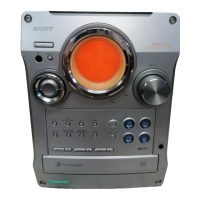
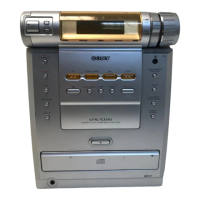
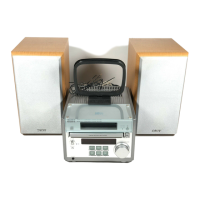
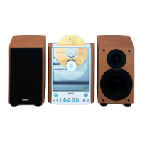
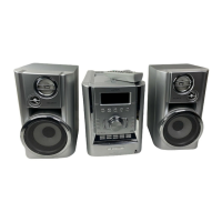
Guide to identifying and locating controls and parts on the unit's front and rear panels.

DISASSEMBLY PROCEDURES

Unit Disassembly Steps

Procedures for removing the front panel, CD mechanism, main board, TCB board, and mechanism deck.

ADJUSTMENTS

Mechanical and Electrical Adjustments

Procedures for mechanical and electrical adjustments for the tape deck section.

IC TERMINAL EXPLANATIONS

DIAGRAMS AND CIRCUIT LAYOUTS

CD Section Block Diagram

Block diagram of the CD section's signal flow and components.

Main Section Schematics

Detailed schematic for the main section, showing component interconnections.

TCB Section Schematics

Schematic diagram for the TCB section, specific to AEP, UK, G, IT, EE models.

BD Section Schematics

Detailed schematic diagram for the BD section, covering optical pick-up and servo circuits.

Audio Section Schematics

Detailed schematic diagram for the audio section, including amplifier and motor control.

EXPLODED VIEWS

Chassis Section Exploded View

Exploded view of the chassis section, illustrating the main structural components and assembly.

Front Panel Section Exploded View

Exploded view of the front panel assembly, showing all external controls and parts.

TC Mechanism Exploded Views

Exploded views of the TC mechanism, detailing tape transport parts and head assembly.

CD Mechanism Exploded Views

Exploded views of the CD mechanism, illustrating disc loading and drive components.

ELECTRICAL PARTS LIST

Related product manuals