HCD-DC1
3232
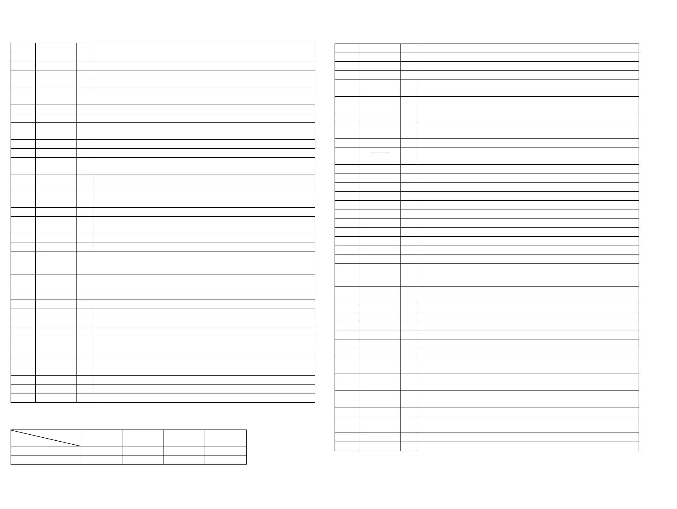
6-17. IC PIN FUNCTION DESCRIPTION
• MAIN BOARD IC801 CXP83124A-050Q (SYSTEM CONTROLLER)
Pin No. Pin Name I/O Description
1
TAPE-END
I
Tape end detect sensor input terminal “H”: input when the tape end detected
2
RDS-IN I Serial data reading clock signal input from the RDS decoder (IC804)
3
REMOCON
I
Sircs remote control signal input from the remote control receiver (IC802)
4
MOT-CON
O
Capstan/reel motor on/off control signal output terminal “H”: motor on
5
C-DATA/
TU-DATA
O
Serial data output to the DSP/SSP (IC101) (at CD function)
PLL serial data output to the PLL IC (LC72137M) (at tuner function)
6 T-MODE I
Head position detect switch input terminal “L”: forward direction, “H”: reverse direction
7
REG-CON
O
Main system power supply on/off contorl signal output terminal “H”: power on
8
C-CLK/TU-CLK O
Serial data transfer clock signal output to the DSP/SSP (IC101) (at CD function)
PLL serial data transfer clock signal output to the PLL IC (LC72137M) (at tuner funcion)
9 JOG-C (BASS)
I Jog dial pulse input from the rotary encoder (C phase input) Not used (fixed at “L”)
10
SOL-CON O Trigger plunger on/off control signal output terminal “H”: plunger on
11
C-SQCK O Subcode Q data reading clock signal output ti the DSP (IC110) (at CD function)
12
C-SQSO/
RDS-DATA
I
Subcode Q data input from the DSP (IC101) (at CD function)
RDS serial data input from the RDS decoder (IC804) (at tuner function)
13 TRAY-OPEN
O Motor drive siganl output to the disc tray open/close motor driver (IC320) “H”: active *1
14 HOLD
O Automatic power control hold signal output to the RF Amp (IC103)
15 TRAY-CLOSE
O Motor drive signal output to the disc tray open/close motor driver (IC309) “H”: active *1
16 JOG-D (BASS)
I Jog dial pulse input from the rotary encoder (D phase input) Not used (fixed at “L”)
17
TUNED I Tuning detection signal input from the LA1837M (IC1) (at tuner function)
18
SENSE2/
TU-COUNT
I
Internal status detection monitor input from the DSP (IC101)
(for MIRR, DFCT2, etc.) (at CD function)
PLL count data input from the PLL IC (LC72137M) (at tuner function)
19
C-LATCH/
TU-CE
O
Serial data latch pulse output to the DSP (IC101) (at CD function)
PLL serial chip enable signal output to the PLL IC (LC72137M) (at tuner function)
20 JOG-B I
Jog dial pulse input from the rotary encoder (RV801 VOLUME) (B phase input)
21 JOG-A I
Jog dial pulse input from the rotary encoder (RV801 VOLUME) (A phase input)
22 AMP-MUTE O
Muting on/off control signal output to the power amplifier (IC101, 201) “H”: muting on
23
JOG-G I Jog dial pulse input from the rotary encoder (G phase input) Not used (fixed at “L”)
24 HP-CHK
I Headphone jack IN/OUT check detection signal input terminal
25
TU-ON O
Power supply on/off control signal output of the tuner section (FM +7.5V)
LED drive signal output of the TUNER/BAND indicator (D853)
“H”: tuner power on (LED on)
26
D. S. G. O
LED drive signal output of the DSG (Dynamic Sound Generator) indicator (D854)
“H”: LED on
27
CD-SYNC
O
LED drive signal output of the CD SYNC indicator (D856) “H”: LED on
28
SCK O Serial data transfer clock signal output to the BD3861FS (IC323)
29
JOG-E I Jog dial pulse input from the rotary encoder (E phase input) Not used (fixed at “L”)
Pin No. Pin Name I/O Description
30
JOG-F I Jog dial pulse input from the rotary encoder (F phase input) Not used (fixed at “L”)
31
JOG-H I Jog dial pulse input from the rotary encoder (H phase input) Not used (fixed at “L”)
32
TC-SW I Half detect (side A and B) switch and cassette in detect switch input terminal (A/D input)
33
TRAY-SW I
Disc tray position detect switch (S1) input terminal (A/D input)
“L”: close position, “M”: open position, “H”: moving
34
KEY3 I
Key input terminal (A/D input) S813 to S816 (TUNER/BAND, TUNING +/-, FUNCTION
input)
35
KEY2 I Key input terminal (A/D input) S801 to S806 (I/
1
, CD
u
/
x
/
M
/
m
/
Z
keys input)
36
KEY1 I
Key input terminal (A/D input)
S807 to S812 (TAPE
n N
/
x
/
M
/
m
/
X
, CD SYNC keys input)
37
SIMUKE/TEST I Destination setting terminal (A/D input)
38
RESET I
System reset signal input from the reset signal generator (IC803) “L”: reset
For several hundreds msec. after the power supply rises, “L”: is input, then it changes to “H”
39 EXTAL1
O Main system clock input terminal (4.19MHz)
40
XTAL1 O Main system clock output terminal (4.19MHz)
41
VSS — Ground terminal
42
XTAL2 O Sub system clock output terminal (500kHz) Not used (open)
43
EXTAL2 I Sub system clock input terminal (500kHz) Not used (fixed at “L”)
44
AVREF I Reference voltage (+5V) input terminal (for A/D conversion)
45
AVSS — Ground terminal (for A/D conversion)
46
VL O Liquid crystal display bias on/off control signal output terminal
47 to 49
VLC3 to VLC1 — Power supply terminal for the liquid crystal display bias
50 to 53 COM0 to COM3
O Common drive signal output to the liquid crystal display (LCD801)
54 to 85
SEG0 to SEG31 O Segment drive signal output to the liquid crystal display (LCD801)
86
C-XRST/FM ON O
Reset signal output to the DSP (IC101) and BA5974FP (IC102) (at CD function)
FM power supply ON/OFF control signal output to the tuner section (FM +7.5V
(at tuner function)
87
REC-MUTE O
Recording muting on/off selection signal output to the Tape section
“H”: muting on, “L”: muting of
88
SDA O Serial data output to the BD861FS (IC323)
89
VDD — Power supply terminal (+5V)
90
NC — Not used (open)
91
VSS — Ground terminal
92
TX O Sub system clock output terminal (32.768kHz)
93
TEX I Sub system clock input terminal (32.768kHz)
94
CD-ON O
Power supply on/off control signal output of the CD section (+5V)
LED drive signal output of the CD
u
indicator (D852) “H”: CD power on (LED on)
95 REC/PB
O
Recording/playback selection signal output to the BA3126N (IC402)
“L”: playback mode, “H”: recording mode
96
L-MUTE O
Line muting on/off selection signal output to the Tape section
“H”: muting on, “L”: muting off
97
AU-MUTE O muting on/off control signal output terminal “H”: muting on
98
TC-ON O
Power supply on/off control signal output of the cassette holder back light
LED drive signal output of the TAPE n N indicator (D855) “H”: back light on (LED on)
99
WP I Wakeup control signal input terminal
100
C-SCOR I Subcode sync (S0+S1) detection signal input from DSP on the CD section (at CD function)
*1 Disc tray open/close motor control
AUX1 AUX2 USB CD-C
TRAY-OPEN (pin qd) “L”“L”“H”“H”
AUDIO_SEL2 (pin qg) “L”“H”“L”“H”
Terminal
Mode