Do you have a question about the Sony CMT-DC1 and is the answer not in the manual?
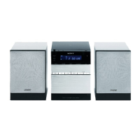
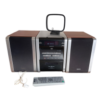
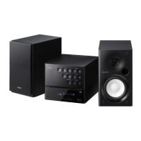
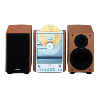
Details the component models comprising the CMT-DC1 system.
Provides a summary of the unit's general physical and electrical characteristics.
Specifies power output and distortion for the amplifier section.
Details specifications for the CD playback mechanism and laser.
Outlines technical parameters for the tape deck and radio tuner functions.
Offers general advice for safe and effective servicing procedures.
Presents a flowchart detailing the step-by-step disassembly sequence.
Guidelines for safely handling sensitive electronic components during repair.
Instructions for performing an AC leakage test to ensure user safety.
Specific precautions for handling the optical pick-up block.
Procedure for safely checking the laser diode output.
Information to help identify different regional models of the unit.
Details the location and function of all controls on the main unit.
Explains the function of each button on the unit and remote.
Step-by-step guide to set or reset the unit's clock.
Lists and describes the function of each button on the remote control.
Step-by-step instructions for removing the upper cover assembly.
Instructions for removing the CD lid mechanism.
Procedure for removing the front panel section.
Steps for disassembling the tape mechanism deck.
Instructions for removing the CD mechanism deck.
Procedure for removing the base unit.
Steps for removing the loading motor board.
Instructions for disassembling the Cam mechanism.
How to perform a cold reset to restore initial settings.
Procedure to test all segments of the LCD display.
Mode for testing tape deck operations.
Mode for testing CD playback operations.
Adjustments related to the tape deck section.
Procedure for aligning the record/playback head azimuth.
Steps to check and adjust the focus bias for CD playback.
Block diagram illustrating the CD servo control circuitry.
Block diagram detailing the main processing and audio sections.
Block diagram for the display and power supply circuits.
Diagrams showing the physical location of each circuit board.
Guidelines for interpreting printed wiring board diagrams.
Guidelines for interpreting schematic diagrams.
Shows waveforms from the CD board for diagnostic purposes.
Displays waveforms from the TC board for diagnostic purposes.
Shows waveforms from the main board for diagnostic purposes.
Printed wiring board layout for the CD section.
Schematic diagram for the CD section.
Printed wiring board layout for the TC section.
Schematic diagram for the TC section.
First part of the main board schematic diagram.
Second part of the main board schematic diagram.
Printed wiring board layouts for main, loading, and headphone boards.
Printed wiring board layouts for switch and I/O switch boards.
Schematic diagram for switch and I/O switch boards.
Printed wiring board layout for the power supply board.
Schematic diagram for the power supply board.
Pin function description for IC801 on the main board.
Block diagram for IC101, the CD signal processor.
Block diagram for IC102, the motor drive IC.
Block diagram for IC103, the RF amplifier.
Block diagram for IC401, the tape amplifier.
Block diagram for power amplifier ICs.
Block diagram for IC320, the loading motor driver.
Block diagram for IC804, the RDS decoder.
Exploded view of the top cover and tape mechanism deck.
Exploded view of the front panel section.
Exploded view of the CD mechanism deck.
Exploded view of the base unit for the CD mechanism.
List of capacitors used on the CD circuit board.
List of connectors and ferrite beads on the CD board.
List of ICs, coils, and transistors on the CD board.
List of resistors used on the CD circuit board.
List of main board capacitors, first part.
List of main board capacitors, second part.
List of connectors, switches, and LEDs on the main board.
Parts for main board loading motor and headphone sections.
List of main board capacitors, third part.
List of diodes, ICs, and transistors on the main board.
List of main board transistors, first part.
List of main board resistors, first part.
List of main board transistors, second part.
List of main board resistors, second part.
List of main board resistors, third part.
List of capacitors used on the TC circuit board.
List of diodes, ICs, and transistors on the TC board.
List of resistors, transformers, coils, and switches on the TC board.
List of components for the power supply board.
Other miscellaneous parts for the TC board.
List of screws, nuts, and other hardware.
List of included accessories and packing materials.
Technical specifications for the SS-CDC1 speaker system.
List of replaceable parts for the SS-CDC1 speaker system.
| Radio Tuner | FM/AM |
|---|---|
| USB Port | No |
| WMA Playback | No |
| Remote Control | Yes |
| CD Player | Yes |
| Cassette Deck | Yes |