EasyManua.ls Logo

Sony DXC-637 - BARS Level Adjustment; Color Vector Adjustment

Sony DXC-637
63 pages
Print Icon
To Next Page IconTo Next Page
To Previous Page IconTo Previous Page
Loading...
HL
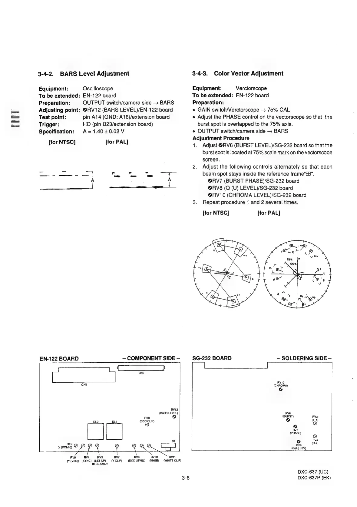
3-4-2.
BARS
Level
Adjustment
Equipment:
Oscilloscope
To
be
extended:
EN-122
board
Preparation:
OUTPUT
switch/camera
side
—
BARS
Adjusting
point:
@RV12
(BARS
LEVEL)/EN-122
board
Test
point:
pin
A14
(GND:
A16)/extension
board
Trigger:
HD
(pin
B23/extension
board)
Specification:
A=1.40+0.02V
[for
NTSC]
[for
PAL]
aa
pee
smn
a
at
yore
o
ie
cam
oo
A A
EN-122
BOARD
RVI2
(BARS
LEVEL)
Rvs
7)
DL2
DLi
{DCC
CLIP)
a
|
|
;
RV6
wvcomp)
@
@
a
Rv5 RV3
RV7
Rvs
RV1O
RV11
(Y
(VBS)}
(SYNC)
(SET
UP)
(¥
CLIP)
(OCCLEVEL)
(KNEE)
(WHITE
CLIP)
NTSC
ONLY
3-4-3.
Color
Vector
Adjustment
Equipment:
Verctorscope
To
be
extended:
EN-122
board
Preparation:
e
GAIN
switch/Verctorscope
>
75%
CAL
e
Adjust
the
PHASE
contro!
on
the
vectorscope
so
that
the
burst
spot
is
overlapped
to
the
75%
axis.
e
OUTPUT
switch/camera
side
—
BARS
Adjustment
Procedure
1.
Adjust
@RV6
(BURST
LEVEL)/SG-232
board
so
that
the
burst
spotis
located
at
75%
scale
mark
on
the
vectorscope
screen.
2.
Adjust
the
following
controls
alternately
so
that
each
beam
spot
stays
inside
the
reference
frame“EB”.
@RV7
(BURST
PHASE)/SG-232
board
@RV8
(Q
(U)
LEVEL)/SG-232
board
@RV10
(CHROMA
LEVEL)/SG-232
board
3.
Repeat
procedure
1
and
2
several
times.
[for
NTSC]
[for
PAL]
$G-232
BOARD
~
SOLDERING
SIDE
—
AV?
(PHASE)
@
RV4
Rve
aa
(Q(u)
LEV)
DXC-637
(UC)
DXC-637P
(EK)