FST-GTK11iP/GTK33iP/RDH-GTK11iP/GTK33iP
5
CAPACITOR ELECTRICAL DISCHARGE PROCESSING
When checking the board, the electrical discharge is necessary for
the electric shock prevention.
Connect the resistors referring to the fi gure below.
• Connetion position
1. MAIN board (Ref. No. C734) (page 5)
2. GTK11-SMPS board (Ref. No. C914) (GTK11iP only)
(page 5)
3. GTK33-SMPS board (Ref. No. C914) (GTK33iP only)
(page 6)
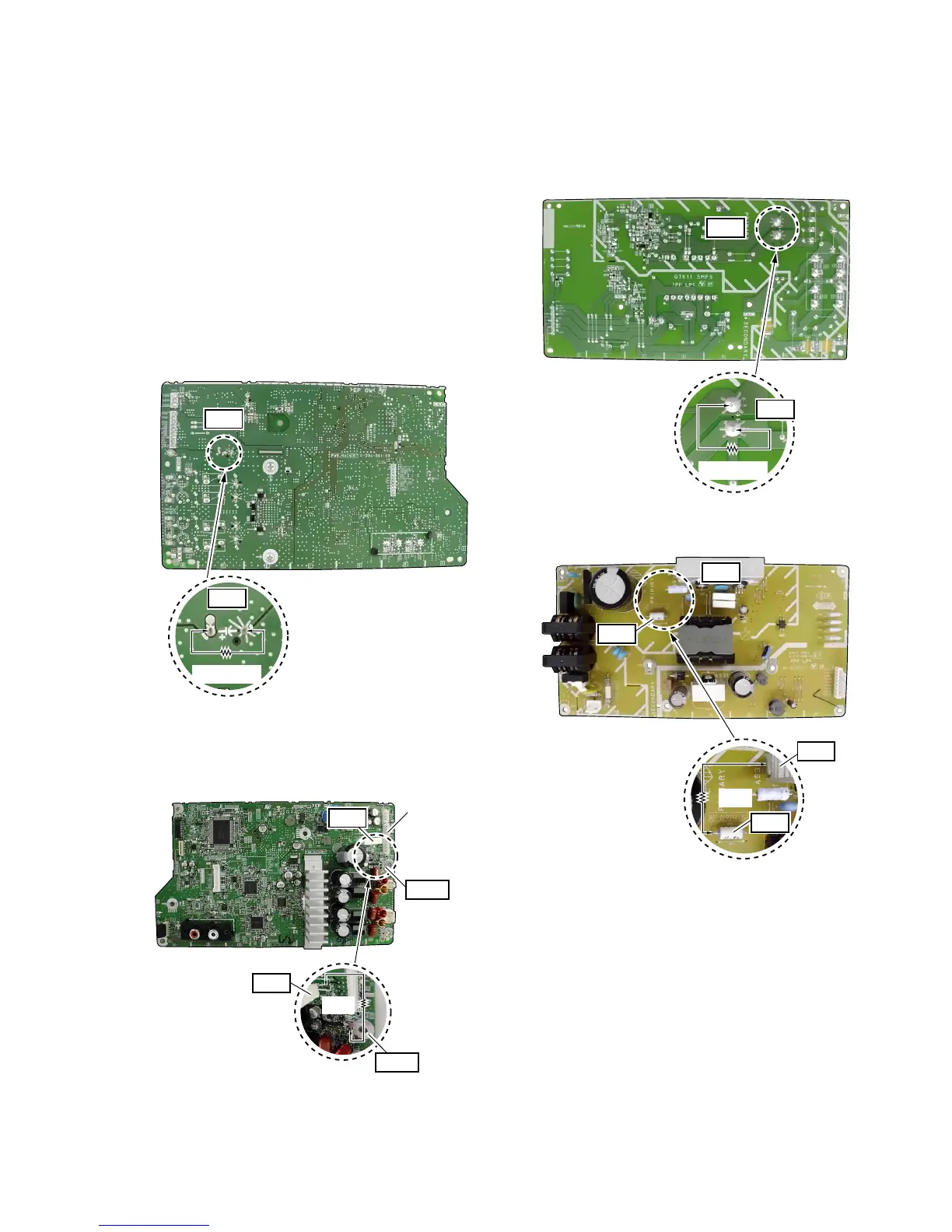
1. MAIN board (Ref. No. C734)
The MAIN board can be discharged by two kinds of following
methods.
1. Both ends of C734.
– MAIN Board (Conductor Side) –
C734
C734
800 :/2 W
2. Ground terminal (ET703) and R727.
Note: When you use this connection, confi rm that the GTK11-SMPS
board (GTK11iP) or the GTK33-SMPS board (GTK33iP) is not
connected with CN811 on the MAIN board.
– MAIN Board (Component Side) –
CN811
Not connect
0 :
R727
ET703
R727
ET703
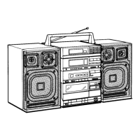
2. GTK11-SMPS board (Ref. No. C914) (GTK11iP only)
The GTK11-SMPS board can be discharged by two kinds of fol-
lowing methods.
1. Both ends of C914.
– GTK11-SMPS Board (Conductor Side) –
C914
C914
800 :/2 W
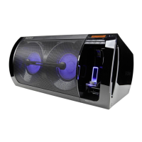
2. Heat sink (A930) and R914.
– GTK11-SMPS Board (Component Side) –
A930
0 :
R914
A930
R914
 Loading...