EasyManua.ls Logo

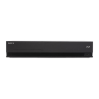
Sony HBD-E770W User Manual

Sony HBD-E770W
114 pages
To Next Page IconTo Next Page
Page #1 background imageLoading...
Page #1 background image
SERVICE MANUAL
Sony Corporation
Audio&Video Business Group
Published by Sony Techno Create Corporation
HBD-E770W
BLU-RAY DISC/DVD RECEIVER
9-889-767-01
2010B05-1
©
2010.02
US Model
Ver. 1.0 2010.02
HBD-E770W is the ampli er, video, BD/DVD/Super Audio
CD/CD system, USB, LAN and tuner section in BDV-E770W.
Model Name Using Similar Mechanism BDP-S370
Mechanism Type
BPX-5
Optical Pick-up Block Name KEM-460AAA
SPECIFICATIONS
Amplifier Section
POWER OUTPUT AND TOTAL HARMONIC
DISTORTION:
(FTC)
Front L + Front R: With 3 ohms loads, both
channels driven, from 180
- 20,000 Hz; rated 60 watts
per channel minimum
RMS power, with no more
than 1% total harmonic
distortion from 250 milli
watts to rated output.
POWER OUTPUT (reference)
Front L/Front R/Center: 167 W (per channel at 3
ohms, 1 kHz)
Subwoofer: 165 W (at 3 ohms, 80 Hz)
Inputs (Analog)
AUDIO (AUDIO IN) Sensitivity: 450/250 mV
Inputs (Digital)
SAT/CABLE (COAXIAL), TV (OPTIC
AL)
Supported formats: LPCM
2CH (up to 48 kHz), Dolby
Digital, DTS
Video Section
Outputs VIDEO: 1 Vp-p 75 ohms
COMPONENT:
Y: 1 Vp-p 75 ohms
PB/CB, PR/CR: 0.7 Vp-p
75 ohms
HDMI OUT: Type A (19
pin)
BD/DVD/Super Audio CD/CD System
Signal format system NTSC
USB Section
(USB) port: Type A (For connecting
USB memory, memory
card reader, digital still
camera, and digital video
camera)
Maximum current: 500 mA
LAN Section
LAN (100) terminal 100BASE-TX Terminal
Tuner Section
System PLL quartz-locked digital
synthesizer
FM tuner section
Tuning range 87.5 MHz - 108.0 MHz
(100 kHz step)
Antenna (aerial) FM wire antenna (aerial)
Antenna (aerial) terminals 75 ohms, unbalanced
Intermediate frequency 10.7 MHz
Design and specifications are subject to change
without notice.
General
Power requirements 120 V AC, 60 Hz
Power consumption On: 130 W
Standby: 0.3 W (at the
Power Saving mode)
Dimensions (approx.) 430 mm × 85 mm × 335
mm (17 in × 3
3
/8 in ×
13
1
/4 in) (w/h/d) incl.
projecting parts
430 mm × 85 mm × 365
mm (17 in × 3
3
/8 in ×
14
3
/8 in) (w/h/d) (incl.
wireless transceiver)
Mass (approx.) 4.7 kg (10 lb 6 oz)
This product incorporates copyright
protection technology that is protected by
U.S. patents and other intellectual property
rights.
Use of this copyright protection technology
must be authorized by Macrovision, and is
intended for home and other limited view-
ing uses only unless otherwise authorized
by Macrovision.
Reverse engineering or disassembly is
prohibited.
This system incorporates with Dolby*
Digital and Dolby Pro Logic (II) adaptive
matrix surround decoder and the DTS**
Digital Surround System.
* Manufactured under license from
Dolby Laboratories.
Dolby, Pro Logic, and the double-D
symbol are trademarks of Dolby
Laboratories.
** Manufactured under license under
U.S. Patent #’s:
5,451,942; 5,956,674; 5,974,380;
5,978,762; 6,226,616; 6,487,535;
7,212,872; 7,333,929; 7,392,195;
7,272,567 & other U.S. and worldwide
patents issued & pending. DTS is a
registered trademark and the DTS
logos, Symbol, DTS-HD and DTS-
HD Master Audio are trademarks of
DTS, Inc. © 1996-2008 DTS, Inc. All
Rights Reserved.
This system incorporates High-De nition
Multimedia Interface (HDMI™) technol-
ogy.
HDMI, the HDMI logo and High-De ni-
tion Multimedia Interface are trademarks
or registered trademarks of HDMI Licens-
ing LLC.
Java and all Java-based trademarks and
logos are trademarks or registered trade-
marks of Sun Microsystems, Inc.
“BD-LIVE” and “BONUSVIEW” are
trademarks of Blu-ray Disc Association.
“Blu-ray Disc” is a trademark.
“Blu-ray Disc,” “DVD+RW,” “DVD-RW,”
“DVD+R,” “DVD-R,” “DVD VIDEO,”
and “CD” logos are trademarks.
“BRAVIA” is a trademark of Sony Corpo-
ration.
“AVCHD” and the “AVCHD” logo are
trademarks of Matsushita Electric Indus-
trial Co., Ltd. and Sony Corporation.
“S-AIR” and its logo are trademarks of
Sony Corporation.
, “XMB,” and “xross media bar” are
trademarks of Sony Corporation and Sony
Computer Entertainment Inc.
“PLAYSTATION” is a trademark of Sony
Computer Entertainment Inc.
Music and video recognition technology
and related data are provided by Grace-
note
®
.
Gracenote is the industry standard in music
recognition technology and related content
delivery. For more information, please visit
www.gracenote.com.
CD, DVD, Blu-ray Disc, and music and
video-related data from Gracenote, Inc.,
copyright © 2000-present Gracenote.
Gracenote Software, copyright ©
2000-present Gracenote. One or more
patents owned by Gracenote apply to this
product and service. See the Gracenote
website for a nonexhaustive list of ap-
plicable Gracenote patents. Gracenote,
CDDB, MusicID, MediaVOCS, the Grace-
note logo and logotype, and the “Powered
by Gracenote” logo are either registered
trademarks or trademarks of Gracenote in
the United States and/or other countries.
w
w
w
.
x
i
a
o
y
u
1
6
3
.
c
o
m
Q
Q
3
7
6
3
1
5
1
5
0
9
9
2
8
9
4
2
9
8
T
E
L
1
3
9
4
2
2
9
6
5
1
3
9
9
2
8
9
4
2
9
8
0
5
1
5
1
3
6
7
3
Q
Q
TEL 13942296513 QQ 376315150 892498299
http://www.xiaoyu163.com

Table of Contents

Question and Answer IconNeed help?

Do you have a question about the Sony HBD-E770W and is the answer not in the manual?

Sony HBD-E770W Specifications

General IconGeneral
TypeHome Theater System
CategoryReceiver
Power Output1000W
Channels5.1
BluetoothYes
HDMI Inputs4
HDMI Outputs1
USB PortYes
Audio Formats SupportedDolby TrueHD, DTS-HD Master Audio, LPCM
Wireless Rear SpeakersYes
3D Pass-ThroughYes
Audio DecodingDolby Digital, DTS
DLNA CertifiedYes
Supported Disc FormatsDVD, CD
ConnectivityEthernet
Dimensions (W x H x D)430 mm

Summary

Specifications

Amplifier Section

Details on amplifier power output and harmonic distortion, including FTC ratings.

BD/DVD/Super Audio CD/CD System

Signal format system and supported formats for disc playback.

USB Section

Information on the USB port, type, and maximum current.

LAN Section

Details on the LAN terminal and its type.

Tuner Section

Specifications for the FM tuner section, including tuning range and antenna details.

General Specifications

General power requirements, consumption, dimensions, and mass of the unit.

Safety Check-Out and Leakage Test

Notes on Chip Component Replacement

Precautions for handling and replacing chip components, especially tantalum capacitors.

Flexible Circuit Board Repairing

Guidelines for repairing flexible circuit boards, including soldering iron temperature.

Safety-Related Component Warning

Warning about components critical to safe operation and replacement instructions.

Caution: Hazardous Radiation Exposure

Warning regarding potential hazardous radiation exposure from improper adjustments.

Servicing Notes

Handling the Optical Pick-Up Block or Base Unit

Precautions for preventing electrostatic breakdown and handling flexible boards.

Laser Diode Emission Check

Guidelines for safely checking the laser diode emission.

Unleaded Solder and Lead Free Mark

Characteristics and precautions for using unleaded solder.

Releasing the Disc Tray Lock

Procedure to release the disc tray lock for demonstration units.

Lens Cleaning Caution

Warning against cleaning the lens with cotton buds to prevent damage.

Capacitor Electrical Discharge Processing

ESD Countermeasure and Repair Preparation

Measures to prevent ESD damage and prepare necessary tools for repair.

Barcode Decoder (BDBUDEC) Installation

Procedure for installing and using the barcode decoder software.

Optical Device Pass-Fail Judgment

Flow of Drive Section Check

Diagnostic flowchart for checking the drive section's operational status.

Flow of Optical Device IOP Check

Diagnostic flowchart for checking the optical device's IOP value.

Optical Device (KEM-460AAA) Replacement Procedure

BD Drive (BPX-5) Parts Replacing

Replacing IC3100 and IC3200 on Main Board

Procedure for replacing IC3100/IC3200 or the main board, including compound application.

Replacing D913, D931, IC901, IC921 on Power Board

Tray Opening and Harness Processing

Section 2 Disassembly

Disassembly Flow

Step-by-step guide for disassembling the unit in numerical order.

Case (EZ) Disassembly

Procedure for removing the outer case (EZ) of the unit.

MB-134 Board Disassembly

Bracket (MB) Block and Fuse Replacement

Front Panel Block and BD Drive Disassembly

Include Board and Back Panel Block Disassembly

Main Board and Audio Board Disassembly

Optical Device (KEM-460AAA) and Wire Replacement

Section 3 Test Mode

Cold Reset and Demo Mode

Procedures for cold reset and demo mode activation/deactivation.

S-AIR ID Setting Display

Procedure to display and set the S-AIR ID.

Panel Test and Amp Test

Procedures for performing panel tests and amplifier tests.

BD Service Mode

Methods to enter and use the BD service mode for diagnostics.

Service Mode Menu Tree

Diag (Device Test)

Tests for devices like USB Host, checking media.

Diag (Video/Audio Test)

Tests for video output (color bar) and audio output (tone sound).

Diag (Audio Input Test)

Tests for digital and analog audio inputs.

Diag (Wireless LAN Test)

Procedure for performing wireless LAN tests (not used for servicing).

Log: Error Log

Viewing error logs and copying them to USB memory.

Factory Initialize

Restores player settings to factory defaults.

Network (Ifconfig and Ping Test)

Diagnosing wired network connections and testing IP address.

System Information Display

Displays system information including model, MAC, and firmware versions.

Drive Operations and Tools

Drive OP Data Write

Purpose of writing OP data into the flash IC.

Servo Parameter Check Menu

Menu for checking servo parameters (Not Used for servicing).

Servo Signal Check Menu

Menu for checking servo signals (Not Used for servicing).

S-Curve Check Menu

Menu for S-Curve check (Not Used for servicing).

Readability Check Menu

Menu for readability check (Not Used for servicing).

OP Position Check Menu

Menu for checking OP position (Not Used for servicing).

OP Check Menu

Menu for verifying OP related data (Not Used for servicing).

Load Eject Aging

Menu for load eject aging test (Not Used for servicing).

Spindle Control Check Menu

Menu for checking spindle control (Not Used for servicing).

FA Test Mode

Menu for FA mode test (Not Used for servicing).

Playback and Network Confirmation

Playback Operation Confirmation with Test Discs

Confirming playback operation using various test discs.

Network Confirmation Procedure

Procedure to confirm network connection by checking IP settings.

Section 4 Electrical Check

FM Tuner Level Check

Procedure for checking FM tuner level using a signal generator.

Section 5 Diagrams

Block Diagram - Servo Section

Overall block diagram of the servo section.

Block Diagram - Memory Section

Block diagram illustrating the memory section components.

Block Diagram - Tuner, S-AIR Section

Block diagram of the tuner and S-AIR sections.

Block Diagram - Audio Section

Block diagram detailing the audio processing circuitry.

Block Diagram - Regulator Section

Block diagram showing the various voltage regulators.

Block Diagram - Panel, Power Supply Section

Block diagram of the panel driver and power supply circuits.

Notes for Printed Wiring Boards and Schematic Diagrams

Circuit Boards Location

Diagram showing the physical locations of major circuit boards.

Notes on Component Indication

Explanation of symbols and notations used in diagrams.

Schematic Diagram - MB-134 Board (1/13)

Schematic Diagram - MB-134 Board (2/13)

Schematic Diagram - MB-134 Board (3/13)

Schematic Diagram - MB-134 Board (4/13)

Schematic Diagram - MB-134 Board (5/13)

Schematic Diagram - MB-134 Board (6/13)

Schematic Diagram - MB-134 Board (7/13)

Schematic Diagram - MB-134 Board (8/13)

Schematic Diagram - MB-134 Board (9/13)

Schematic Diagram - MB-134 Board (10/13)

Schematic Diagram - MB-134 Board (11/13)

Schematic Diagram - MB-134 Board (12/13)

Schematic Diagram - MB-134 Board (13/13)

Printed Wiring Board - MB-134 Board (Component Side)

Printed Wiring Board - MB-134 Board (Conductor Side)

Printed Wiring Board - Audio Board

Schematic Diagram - Audio Board

Printed Wiring Board - Main Board (Component Side)

Printed Wiring Board - Main Board (Conductor Side)

Schematic Diagram - Main Board (1/5)

Schematic Diagram - Main Board (2/5)

Schematic Diagram - Main Board (3/5)

Schematic Diagram - Main Board (4/5)

Schematic Diagram - Main Board (5/5)

Key Board Sections

Printed Wiring Boards - Key Section

Layout of the key board's printed wiring board (component side).

Schematic Diagram - Key Section

Schematic diagram detailing the key board's circuitry.

Waveforms and REG Board Diagrams

Waveforms (Main and Include Boards)

Illustrations of waveforms for main and include boards.

Printed Wiring Board - REG Board

Layout of the REG board's printed wiring board (component side).

Schematic Diagram - REG Board

Printed Wiring Board - Include Board

Schematic Diagram - Include Board

Printed Wiring Board - FL Board

Schematic Diagram - FL Board

Printed Wiring Board - Power Board

Schematic Diagram - Power Board

IC Block Diagrams - MB-134 Board

IC303 MM3141CNRE Block Diagram

Block diagram of the MM3141CNRE IC.

IC307 MM3293DNRE Block Diagram

Block diagram of the MM3293DNRE IC.

IC308 MP2301ENE-LF-Z Block Diagram

Block diagram of the MP2301ENE-LF-Z IC.

IC309, 310 TPS54325PWPR Block Diagrams

Block diagrams of the TPS54325PWPR ICs.

IC1001 NJM2878F3-33 (TE2) Block Diagram

Block diagram of the NJM2878F3-33 IC.

IC1002 NJM2828F3-05 Block Diagram

Block diagram of the NJM2828F3-05 IC.

IC3100, 3200 CXD9981TN Block Diagrams

Block diagrams of the CXD9981TN ICs.

IC400 TK11133CSCL-G Block Diagram

Block diagram of the TK11133CSCL-G IC.

IC402 TK72270CSCL-GH Block Diagram

Block diagram of the TK72270CSCL-GH IC.

IC201 TK11133CSCL-G Block Diagram

Block diagram of the TK11133CSCL-G IC.

IC202 SI-3010KM-TLS Block Diagram

Block diagram of the SI-3010KM-TLS IC.

IC203 - 205 AK4127VF-E2 Block Diagrams

Block diagrams of the AK4127VF-E2 ICs.

IC Pin Function Description - MB-134 BOARD IC101 CXD9983GG

Section 6 Exploded Views

Case, Front Panel Section Exploded View

Exploded view of the unit's case and front panel assembly.

MB-134 Board Section Exploded View

Exploded view of the MB-134 board assembly.

Back Panel Section Exploded View

Exploded view of the back panel components.

Main Board Section Exploded View

Exploded view of the main board and its connected parts.

BD Drive Section (BPX-5) Exploded View

Exploded view of the BD drive mechanism (BPX-5).

Section 7 Electrical Parts List

Capacitor List

List of capacitors used in the circuit with their part numbers and specifications.

Connector List

List of connectors used in the circuit with their part numbers.

Diode List

List of diodes used in the circuit with their part numbers.

IC List

List of integrated circuits used in the circuit with their part numbers.

Coil List

List of coils used in the circuit with their part numbers.

Transistor List

List of transistors used in the circuit with their part numbers.

Resistor List

List of resistors used in the circuit with their part numbers and values.

Revision History

Related product manuals