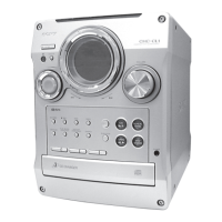
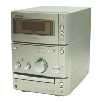
HCD-C5
AEP Model
UK Model
E Model
Australian Model
SERVICE MANUAL
MICRO HI-FI COMPONENT SYSTEM
Sony Corporation
Home Audio Company
Shinagawa Tec Service Manual Production Group
9-873-244-02
2001I1600-1
© 2001.9
SPECIFICATIONS
Ver 1.1 2001. 09
HCD-C5 is the Amplifier, CD player, MD
Deck and Tuner section in CMT-C5.
Model Name Using Similar Mechanism New
CD Mechanism Type TN-CCD1001Z
Base Unit Name TT BASE ASSY
Optical Pick-up Name OPTIMA-720L1E
Model Name Using Similar Mechanism New
MD Mechanism Type MDM-7B4M
Optical Pick-up Name KMS-260E/Z-NP
CD
Section
MD
Section
Amplifier section
European model:
DIN power output (rated): 15 + 15 W
(6 ohms at 1 kHz, DIN)
Continuous RMS power output (reference):
20 + 20 W
(6 ohms at 1 kHz, 10%
THD)
Music power output (reference):
45 + 45 W
Australian model:
The following measured at 230 V AC, 60 Hz
DIN power output (rated): 15 + 15 W
(6 ohms at 1 kHz, DIN)
Continuous RMS power output (reference):
20 + 20 W
(6 ohms at 1 kHz, 10%
THD)
Other models:
The following measured at 220 V AC, 60 Hz
DIN power output (rated): 15 + 15 W
(6 ohms at 1 kHz, DIN)
Continuous RMS power output (reference):
20 + 20 W
(6 ohms at 1 kHz, 10%
THD)
Inputs
TAPE IN (stereo minijack):
Sensitivity 250 mV,
impedance 47 kilohms
DIGITAL OPTICAL IN (Supported sampling
frequencies: 32 kHz, 44.1 kHz and 48 kHz)
Outputs
TAPE OUT (stereo minijack):
Sensitivity 250 mV,
impedance 1 kilohmes
PHONES (stereo minijack):
Accepts headphones with
an impedance of 8 ohms
or more
CD player section
System Compact disc and digital
audio system
Laser Semiconductor laser
(λ = 780 nm)
Emission
duration: continuous
Frequency response 2 Hz – 20 kHz
MD deck section
System MiniDisc digital audio
system
Laser Semiconductor laser
(λ=780 nm)
Emission duration:
continuous
Sampling frequency 44.1 kHz
Frequency response 5 Hz – 20 kHz
Tuner section
FM stereo, FM/AM superheterodyne tuner
FM tuner section
Tuning range 87.5 – 108.0 MHz
(50-kHz step)
Antenna FM wire antenna
Antenna terminals 75 ohm unbalanced
Intermediate frequency 10.7 MHz
AM tuner section
Tuning range
European model: 531 – 1,602 kHz
(with the tuning interval
set at 9 kHz)
Other models: 530 – 1,710 kHz
(with the tuning interval
set at 10 kHz)
531 – 1,602 kHz
(with the tuning interval
set at 9 kHz)
Antenna AM loop antenna, external
antenna terminal
Intermediate frequency 450 kHz
General
Power requirements
European model: 230 V AC, 50/60 Hz
Australian model: 230 V AC, 50/60 Hz
Other models: 220 V AC , 50/60 Hz
Power consumption
European model: See the nameplate
0.5 W (at the power
saving mode)
Other models: See the nameplate
Dimensions (w/h/d) Approx. 145 × 125 ×
273 mm incl. projecting
parts and controls
Mass Approx. 4.5 kg
Supplied accessories Remote commander (1)
AM loop antenna (1)
FM wire antenna (1)
Design and specifications are subject to change
without notice.