HCD-DZ30
7
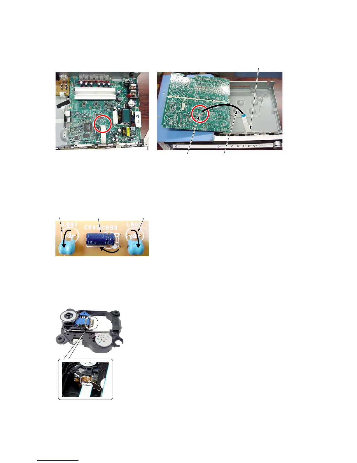
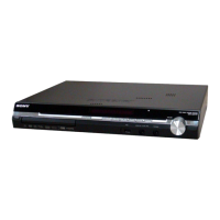
MAIN board service position
Please take the above-mentioned position in the repair of MAIN board.
In that case, it is necessary the following extension cable during CN801 on FL board and CN509 on MAIN board.
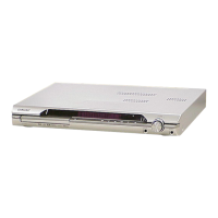
Note on replacement of C803, L801, and L802
Please fold in the directtion of the arrow and set up at replacement of C803, L801, and L802 on FL board.
L801 L802C803
+
–
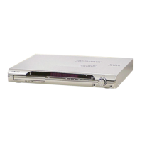
Precaution when installing a new OP unit /
Precaution before unsoldering the static electricity prevention solder bridge
When installing a new OP unit, be sure to connect the fl exible printed circuit board fi rst of all
before removing the static electricity prevention solder bridge by unsoldering.
Remove the static electricity prevention solder bridge by unsoldering after the fl exible printed
circuit board has already been connected.
(Do not remove nor unsolder the solder bridge as long as the OP unit is kept standalone.)
CN509
CN801
extension cable
jig P/N: J-2501-231-A
(pitch 1.00 mm/15p/300L)