3
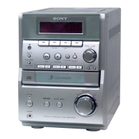
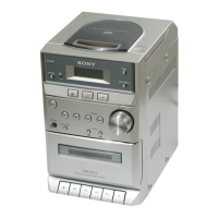
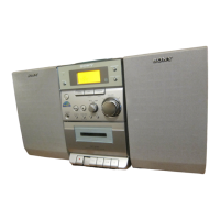
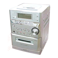
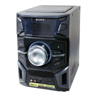
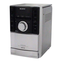
HCD-EP707
TABLE OF CONTENTS
1. SERVICING NOTES ................................................ 4
2. GENERAL ................................................................... 5
3. DISASSEMBLY
3-1. Disassembly Flow ........................................................... 6
3-2. Side (Panel) ..................................................................... 7
3-3. Top Cabinet Section ........................................................ 7
3-4. Tape Mechanism Deck (CRL4349) ................................ 8
3-5. Front Panel Section ......................................................... 8
3-6. MAIN Board ................................................................... 9
3-7. CD Mechanism Deck (CMCJ-0132) .............................. 9
3-8. REGULATOR Board ...................................................... 10
3-9. POWER AMP Board....................................................... 10
3-10. Cover ............................................................................... 11
3-11. Drawer ............................................................................. 12
3-12. Belt (Gray/Black) ............................................................ 13
3-13. Optical Block .................................................................. 13
4. ELECTRICAL ADJUSTMENTS......................... 14
5. DIAGRAMS
5-1. Block Diagram – TUNER Section – ............................. 16
5-2. Block Diagram – TAPE DECK Section – ..................... 17
5-3. Block Diagram – MAIN Section – ................................ 18
5-4. Block Diagram
– DISPLAY/POWER SUPPLY Section – ...................... 19
5-5. Note for Printed Wiring Boards and
Schematic Diagrams ....................................................... 20
5-6. Printed Wiring Boards – MAIN Section – .................... 21
5-7. Schematic Diagram – MAIN Section (1/2) –................ 22
5-8. Schematic Diagram – MAIN Section (2/2) –................ 23
5-9. Printed Wiring Boards – POWER AMP Section – ...... 24
5-10. Schematic Diagram – POWER AMP Section – ............ 25
5-11. Printed Wiring Boards – DISPLAY Section – .............. 26
5-12. Schematic Diagram – DISPLAY Section – ................... 27
5-13. Printed Wiring Boards – REGULATOR Section – ....... 28
5-14. Schematic Diagram – REGULATOR Section – ........... 29
5-15. IC Pin Function Description ........................................... 31
6. EXPLODED VIEWS
6-1. Panel Section ................................................................... 33
6-2. Front Panel Section ......................................................... 34
6-3. Top Cabinet Section ........................................................ 35
6-4. Chassis Section ............................................................... 36
6-5. CD Section ...................................................................... 37
7. ELECTRICAL PARTS LIST ............................... 38
Ver 1.1