EasyManua.ls Logo

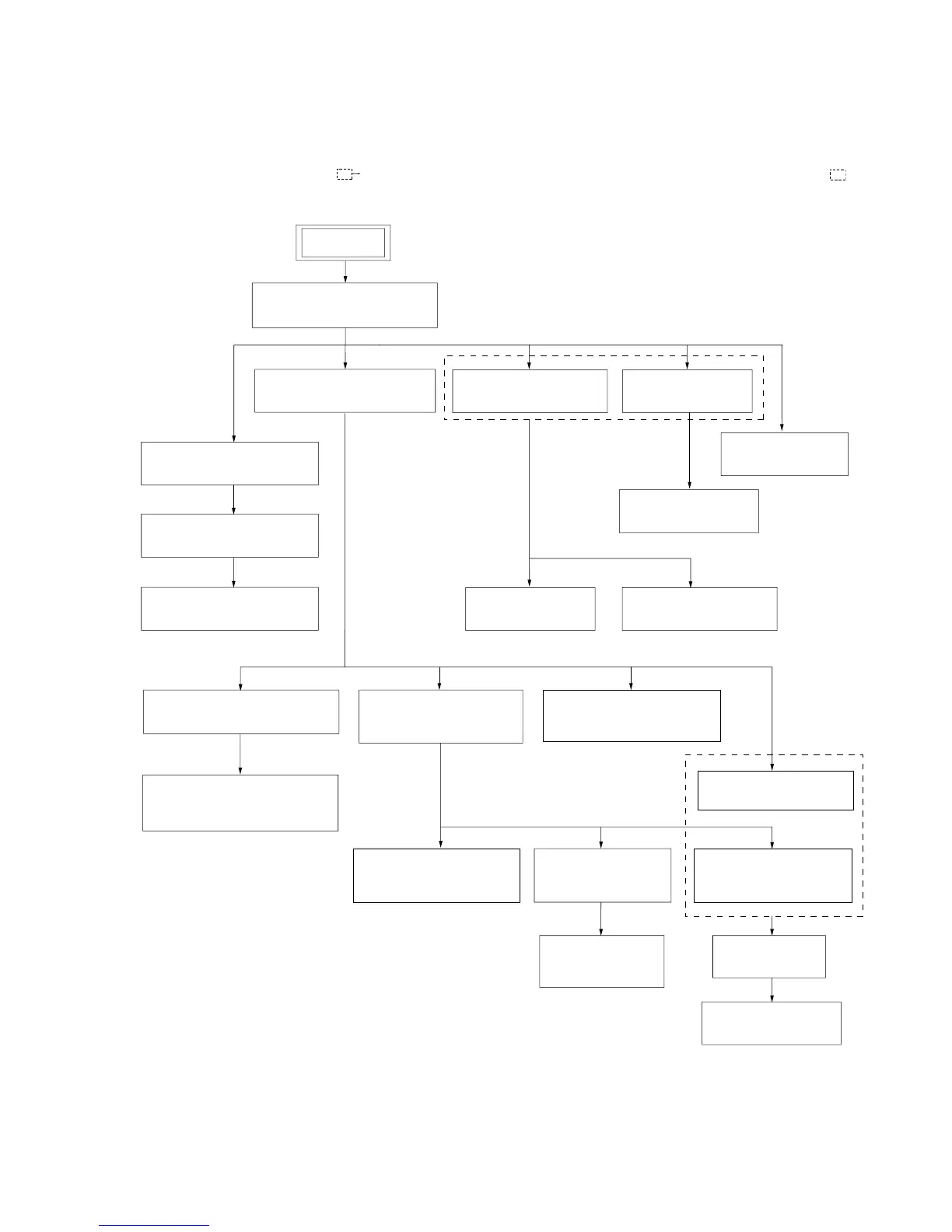
Sony HCD-FX900W - SECTION 3 DISASSEMBLY; 3-1. DISASSEMBLY FLOW

Sony HCD-FX900W
146 pages
Print Icon
To Next Page IconTo Next Page
To Previous Page IconTo Previous Page
Loading...
15
HCD-FX900W
SECTION 3
DISASSEMBLY
3-1. DISASSEMBLY FLOW
3-3.JACK BOARD,
FRONT PANEL SECTION
(Page 17)
3-11. POWER BOARD
(Page 22)
3-8. DMB12 BOARD
(Page 20)
3-10.SP BOARD
(Page 22)
3-9. MAIN BOARD
(Page 21)
3-6. I/O BOARD,
D.C. FAN
(Page 19)
3-7. DIAT TX XM BOARD
(Page 20)
3-4.KEY BOARD, FL BOARD
(Page 18)
3-5.BUTTON
(DISC/PLAY/POWER)
(Page 19)
3-12. DVD MECHANISM DECK
(CDM69EH-DVBU101)
(Page 23)
SET
3-2. TOP PANEL, SIDE PANEL
(Page 16)
3-13.BASE UNIT(DVBU101)
(Page 23)
3-20.RUBBER ROLLER
(SLIDER) ASSY
(Page 27)
3-21.TIMING BELT
(FRONT/REAR)
(Page 27)
3-22.CAM (GEAR)
(Page 28)
3-23.SENSOR BOARD
(Page 28)
3-15.SW BOARD,
BRACKET (TOP) ASSY
(Page 24)
3-14.OPTICAL PICK-UP
(KHM-310CAB)
(Page 24)
3-19.MOTOR (MODE)
ASSY (MODE) (M771)
(Page 26)
3-18.MOTOR (ROLLER)
ASSY (ROLLER) (M781)
(Page 26)
3-17.MOTOR (STOCKER)
ASSY (STOCKER) (M761)
(Page 25)
3-16.RELAY BOARD
(Page 25)
•This set can be disassembled in the order shown below.
•The dotted square with arrow ( ) prompts you to move to the next job when all of the works within the dotted square ( ) are
completed.

Table of Contents