HCD-HDX285/HDX287WC/HDX585/HDX587WC/HDX589W/HDX685/HDX686W
77
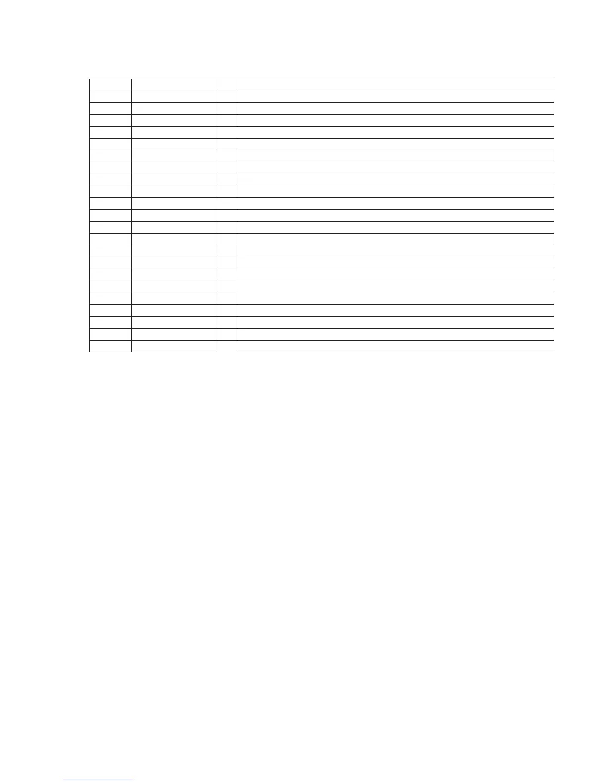
Pin No. Pin Name I/O Description
1 CTLIO I Input/output selection signal input terminal "L": input, "H": output Fixed at "L": in this set
2 RESET_B I Reset signal input from the system controller "L": reset
3 CLK I Serial data transfer clock signal input from the system controller
4 LATCH I Serial data latch pulse signal input from the system controller
5 to 7 P15 to P13 I Not used
8 P12 I Main tray open detection switch input terminal "L": main tray is opened
9 P11 I Sub tray out detection switch input terminal "L": sub tray out
10 P10 I Sub tray in detection switch input terminal "L": sub tray in
11 P9 I Main tray close detection switch input terminal "L": main tray is closed
12 P8 I Disc insert detection signal input terminal
13 LATCHO O Serial data latch pulse signal output to the audio/video controller
14 CLKO O Serial data transfer clock signal output to the audio/video controller
15 DO1 O Serial data output to the audio/video controller
16 DI2 I Serial data input terminal Not used
17, 18 P7, P6 O Not used
19, 20 P5, P4 O Stocker up/down motor drive signal output terminal
21, 22 P3, P2 O Not used
23, 24 P1, P0 O Loading motor drive signal output terminal
25 DO2 O Serial data output to the audio/video controller
26 DI2 I Serial data input from the system controller
27 VSS - Ground terminal
28 VCC - Power supply terminal (+3.3V)
SERIPARA BOARD IC001 BH2210FV-E2 (CHANGER CONTROLLER)


 To Next Page