27
HCD-M10
4. After the adjustments, apply suitable locking compound to the
parts adjusted.
Adjustment Location:
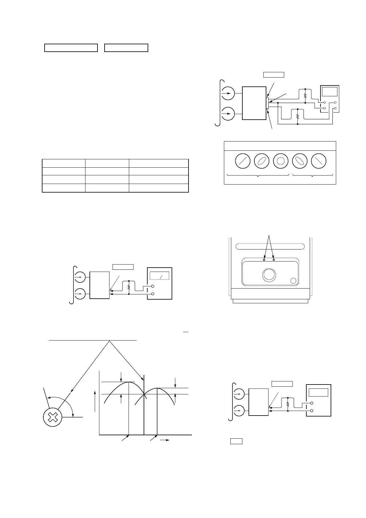
3. Mode: Playback
test tape
P-4-A100
(10kHz, –10dB)
oscilloscope
set
Waveform of oscilloscope
in phase 45
°
90
°
135
°
180
°
good
wrong
GND
R-ch
L
R
J301
PHONES
Output Terminal
32
Ω
32
Ω
Tape Speed Check
Procedure:
1. MODE : Playback.
test tape
WS-48B
(3kHz, 0dB)
J301
PHONES
Output Terminal
frequency
counter
set
32
Ω
(Top view)
Adjustment point
2. Insert the WS-48B into deck.
3. Press the Y button of deck.
4. Check the reading of frequency counter becomes 3000 ± 90 Hz.
Sample Value of Wow and flutter
W.RMS (JIS) less than 0.3%
(test tape: WS-48B)
Note: Standard Volume Point is –10 dBs at PHONES Output Level (32Ω
load resistance) during playbacking P-4-L300 Test Tape.
(DSG OFF, TREBLE/BASS CENTER)
Record/Playback Head Azimuth Adjustment
Procedure:
1. Mode : Playback
2. Turn the adjustment screw and check output peaks. If the peaks
do not match for L-CH and R-CH, turn the adjustment screw
so
that outputs match within 1 dB of peak.
L-CH
peak
R-CH
peak
screw
position
output
level
within
1 dB
L-CH
peak
R-CH
peak
screw
position
within 1dB
DECK SECTION 0 dB=0.775V
1. Demagnetize the record/playback head with a head demagne-
tizer.
2. Do not use a magnetized screwdriver for the adjustments.
3. After the adjustments, apply suitable locking compound to the
parts adjusted.
4. The adjustments should be performed with the rated power sup-
ply voltage unless otherwise noted.
5. The adjustments should be performed in the order given in this
service manual. (As a general rule, playback circuit adjustment
should be completed before performing recording circuit ad-
justment.)
6. The adjustments should be performed for both L-CH and R-
CH.
7. Switches and controls should be set as follows unless other-
wise specified.
SECTION 5
ELECTRICAL ADJUSTMENTS
test tape
P-4-A100
(10kHz, –10dB)
J301
PHONES
Output Terminal
level meter
set
+
–
32
Ω
Tape
P-4-A100
WS-48B
P-4-L300
10 kHz, –10 dB
3 kHz, 0 dB
315 Hz, 0 dB
Azimuth Adjustment
Tape Speed Adjustment
Level Adjustment
Signal Used for