31
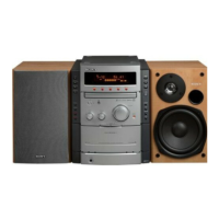
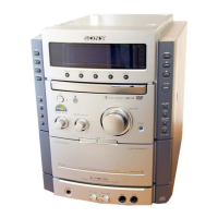
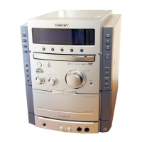
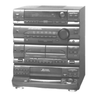
HCD-NE3
Pin No. Pin Name I/O Description
41
TA LED O
LED drive signal output terminal
42
TU LED O
LED drive signal output terminal
43
CD LED O
LED drive signal output terminal
44
NC
—
Not used
45 to 53 SEG33 to SEG25 O Segment drive signal output to the fluorescent indicator tube
54
VDD2 —
Power supply terminal (+3.1V)
55 VSS2 — Ground terminal
56 to 79 SEG24 to SEG1 O Segment drive signal output to the fluorescent indicator tube
80 BIAS3 I
Power supply output for the liquid crystal display bias
81 LCD BIAS2 I
Power supply output for the liquid crystal display bias
82 LCD BIAS1 I
Power supply output for the liquid crystal display bias
83 to 86
LCD COM0 to
LCD COM3
O Common drive signal output to the liquid crystal display (D621)
87, 88 NC
—
Not used
89 VSS3 — Ground terminal
90 VDD3 —
Power supply terminal (+3.1V)
91 TA PLAY SW I PLAY switch signal input from the tape mechanism deck
92 TA END SW I END switch signal input from the tape mechanism deck
93 TA MOTOR
O
Capstan/reel motor on/off control signal output terminal “H”: motor on
94
TA REC/PLAY O
Recording/playback selection signal output terminal “H”: playback mode, “L”: recording mode
95
TA BIAS O
Recording bias on/off selection signal output terminal “H”: bias on, “L”: bias off
96
TA SOL O
Trigger plunger on/off control signal output terminal “H”: plunger on
97
BACK LIGHT ON
O
LED drive signal output terminal for the LCD back light
98
AMP STBY O
Standby control signal output to the power amplifier
99
AMP MUTE
O Tuner muting on/off control signal output to the power amplifier
100 AU MUTE O Line muting on/off control signal output terminal Not used