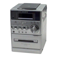
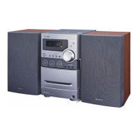
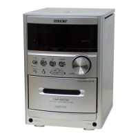
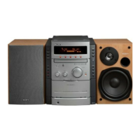
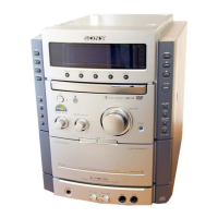
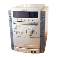
HCD-NE3
3
TABLE OF CONTENTS
1. SERVICING NOTES ................................................ 4
2. GENERAL
Location of Controls ....................................................... 6
3. DISASSEMBLY
3-1. Disassembly Flow ........................................................... 8
3-2. Rear Cabinet .................................................................... 8
3-3. Top Panel Assy ................................................................ 9
3-4. Front Panel Assy ............................................................. 9
3-5. Base Unit (BU-K7BD80B) ............................................. 10
3-6. Mechanical Deck............................................................. 10
3-7. MAIN Board ................................................................... 11
3-8. AMP Board ..................................................................... 11
4. TEST MODE.............................................................. 12
5. ELECTRICAL CHECK .......................................... 14
6. DIAGRAMS
6-1. Block Diagram – CD SERVO Section – ....................... 15
6-2. Block Diagram – MAIN Section – ................................ 16
6-3. Note for Printed Wiring Boards
and Schematic Diagrams ................................................ 17
6-4. Printed Wiring Board – BD Board – ............................. 18
6-5. Schematic Diagram – BD Board – ................................ 19
6-6. Printed Wiring Boards – MAIN Section – .................... 20
6-7. Schematic Diagram – MAIN Section –......................... 21
6-8. Printed Wiring Boards – AMP Section –....................... 22
6-9. Schematic Diagram – AMP Section – ........................... 23
6-10. Printed Wiring Boards – PANEL Section – .................. 24
6-11. Schematic Diagram – PANEL Section – ....................... 25
6-12. Printed Wiring Board – POWER Board – ..................... 26
6-13. Schematic Diagram – POWER Board – ........................ 27
7. EXPLODED VIEWS
7-1. Panel Section ................................................................... 32
7-2. Front Panel Assy-1 .......................................................... 33
7-3. Front Panel Assy-2 .......................................................... 34
7-4. Top Panel Assy ................................................................ 35
8. ELECTRICAL PARTS LIST ............................... 36