45
HCD-PX333
8. Press the . “R” or > “R” button so that the waveform of
the oscilloscope becomes the specified value.
(When the . “R” or > “R” button is pressed, the of
“EFB=
” changes and the waveform changes) In this
adjustment, waveform varies at intervals of approx. 2%. Adjust
the waveform so that the specified value is satisfied as much as
possible.
(Write power traverse adjustment)
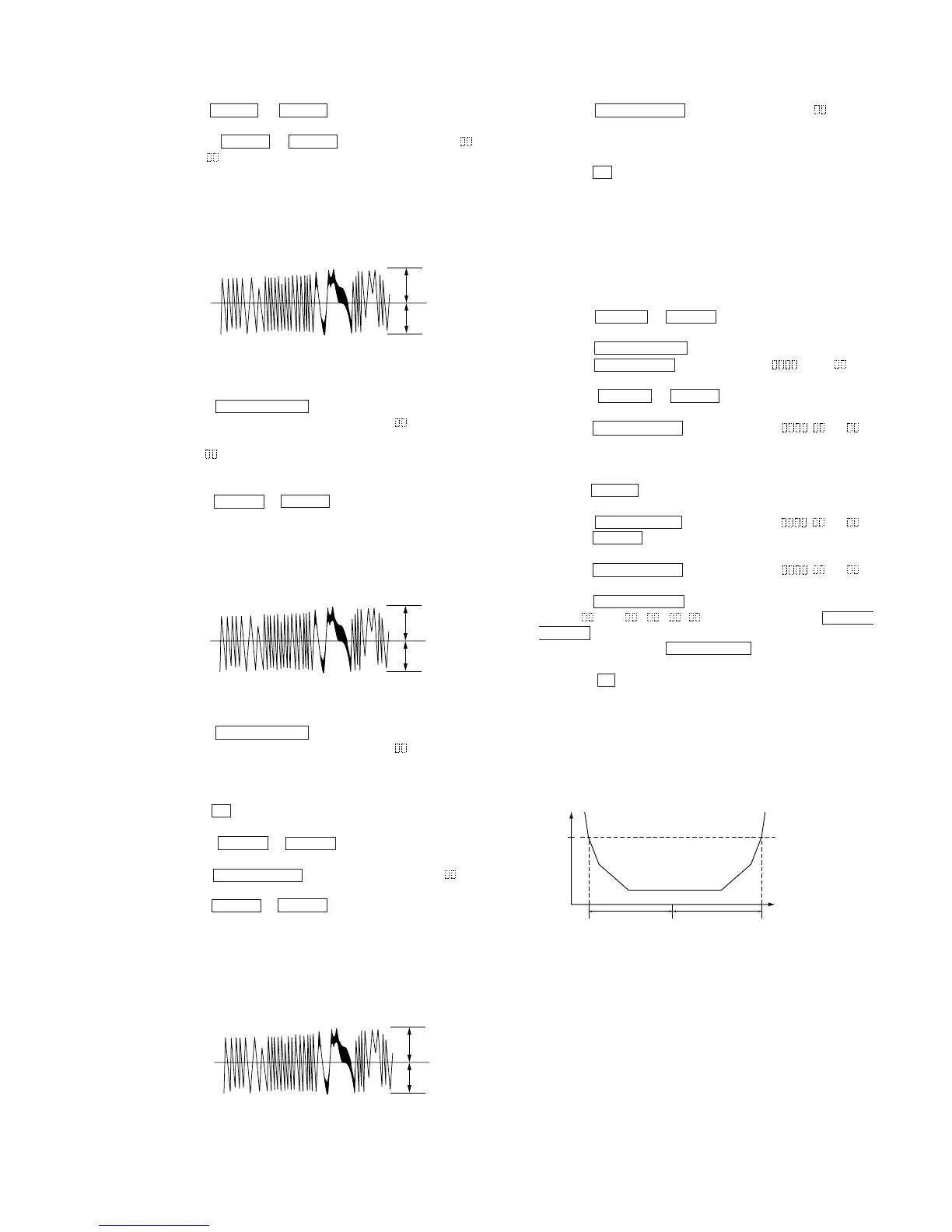
Traverse Waveform
9. Press the ENTER/YES “R” button, and save the adjustment
results in the non-volatile memory. (“EFB = SAVE” will be
displayed for a moment)
10. “EFB = MO-P” will be displayed.
The optical pick-up moves to the pit area automatically and
servo is imposed.
11. Press the . “R” or > “R” button until the waveform of
the oscilloscope moves closer to the specified value.
In this adjustment, waveform varies at intervals of approx. 2%.
Adjust the waveform so that the specified value is satisfied as
much as possible.
Traverse Waveform
12. Press the ENTER/YES “R” button, and save the adjustment
results in the non-volatile memory. (“EFB = SAVE” will be
displayed for a moment)
Next “EF MO ADJUST” (C07) is displayed. The disc stops
rotating automatically.
13. Press the Z (MD) button and take out the disc.
14. Load the check disc (TDYS-1).
15. Press the . “R” or > “R” button to display “EF CD
ADJUST” (C08).
16. Press the ENTER/YES “R” button to display “EFB = CD”.
Servo is imposed automatically.
17. Press the . “R” or > “R” button so that the waveform of
the oscilloscope moves closer to the specified value.
In this adjustment, waveform varies at intervals of approx. 2%.
Adjust the waveform so that the specified value is satisfied as
much as possible.
Traverse Waveform
18. Press the ENTER/YES “R” button, display “EFB = SAVE”
for a moment and save the adjustment results in the non-volatile
memory.
Next “EF CD ADJUST” (C08) will be displayed.
19. Press the Z (MD) button and take out the check disc.
Adjustment Location: BD (MD) board (see page 47)
13.FOCUS BIAS ADJUSTMENT
Procedure:
1. Load the continuously-recorded disc. (Refer to “5. USING
THE CONTINUOUSLY RECORDED DISC” (See page 40))
2. Press the . “R” or > “R” button to display “CPLAY2
MODE” (C36).
3. Press the ENTER/YES “R” button to display “CPLAY2MID”.
4. Press the MENU/NO “R” button when “C = AD = )” is
displayed.
5. Press the . “R” or > “R” button to display “FBIAS
ADJUST” (C09).
6. Press the ENTER/YES “R” button to display “ / a = ”.
The first four digits indicate the C1 error rate, the two digits
after “/ ” indicate ADER, and the 2 digits after “a =” indicate
the focus bias value.
7. Press the > “R” button and find the focus bias value at which
the C1 error rate becomes about 200 (refer to Note 2).
8. Press the ENTER/YES “R” button to display “ / b = ”.
9. Press the . “R” button and find the focus bias value at which
the C1 error rate becomes about 200.
10. Press the ENTER/YES “R” button to display “ / c = ”.
11. Check that the C1 error rate is below 20 and ADER is 00. Then
press the ENTER/YES “R” button.
12. If the “(
)” in “ - - ( )” is above 20, press the ENTER/
YES “R” button.
If below 20, press the MENU/NO “R” button and repeat the
adjustment from step 2.
13. Press thet Z (MD) button and take out the disc.
Note 1: The relation between the C1 error and focus bias is as shown in
the following figure. Find points A and B in the following figure
using the above adjustment. The focal point position C is auto-
matically calculated from points A and B.
Note 2: As the C1 error rate changes, perform the adjustment using the
average vale.
A
B
VC
Specification A = B
A
B
VC
Specification A = B
A
B
VC
Specification A = B
C1 error
about
200
B
CA
Focus bias value


 To Next Page