5
Locations and Functions
of Parts
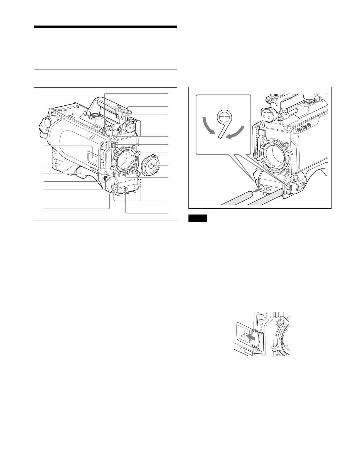
Front Left
a VF (viewfinder) connector (20-pin)
Connect the cable of the viewfinder (not supplied).
b Accessory shoe
To attach an accessory using a 1/4-inch screw.
c Viewfinder left-right positioning ring
Locks the left-right position of the viewfinder.
Loosen this ring to adjust the viewfinder position.
d Viewfinder front-rear positioning lever and LOCK knob
Locks the front-rear position of the viewfinder.
Loosen the lever and knob to adjust the viewfinder position.
For details about adjusting the viewfinder position, see
“Attaching a Viewfinder” (page 12).
e Lens cable clamp
To secure the cable of the lens (not supplied).
f Lens fixing lever (PL)
To secure the lens in the lens mount.
g Lens mount cap
Always keep the lens mount covered with this cap when a lens
is not attached. The cover can be removed by moving the lens
fixing lever upwards.
h Lens mount
To attach a lens.
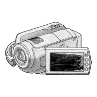
i Rod clamp
Used when attaching and removing φ15 rods.
When attaching, turn the rod lock levers clockwise to secure
the rods.
When removing, turn the rod lock levers counterclockwise to
loosen the levers.
If a lever is in a position that makes it difficult to turn, pull out
the lever to a position where it will be easier to operate. Then,
push the lever back in.
Do not overtighten the rod lock levers when not using rods.
j RET 2 (return video 2) button
When this button is pressed, the picture on the viewfinder
screen changes to the return video signal selected with the
RET 2 select switch (page 8 (JN/SY models) or page 8 (CE/
CN models)) on the operation panel on the rear of the camera.
You can also assign other functions to this button, using the
menu displayed on the viewfinder screen.
k Camera number
Insert the supplied camera number label to display the camera
number.
l NETWORK TRUNK connector (RJ-45 8-pin)
Connects a device connected to the CCU’s NETWORK
TRUNK connector to the network.
m Shoulder pad
You can adjust the position toward the front or rear.
For details, see “Adjusting the Shoulder Pad Position”
(page 15).
c
d
e
f
g
h
i
j
a
b
k
l
m
n
o
p
Note
To loosen, turn
counterclockwise.
To tighten, turn
clockwise