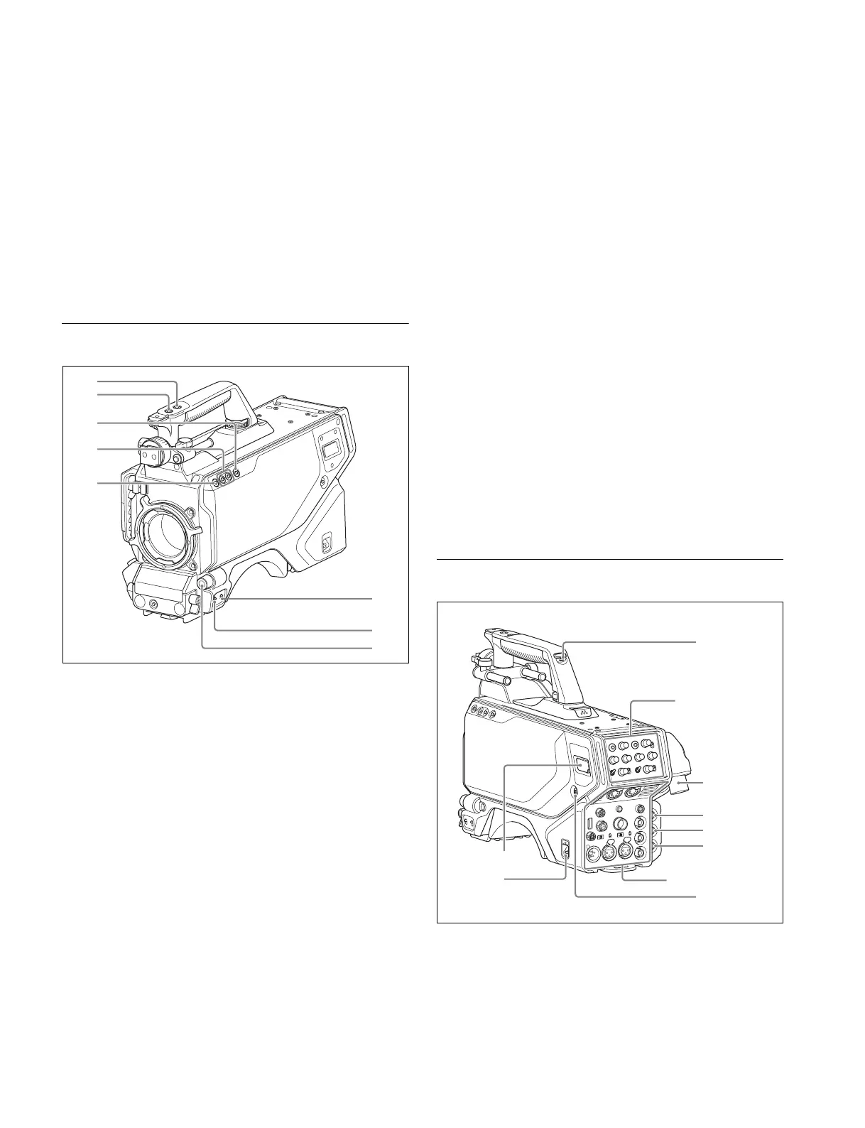
6
n RET 1 (return video 1) button
The return video 1 signal from the camera control unit is
monitored on the viewfinder screen while this button is
pressed. It functions the same as the RET 1 buttons on the
handle (page 6) and on the operation panel on the rear of the
camera (page 8 (JN/SY models) or page 8 (CE/CN models)).
You can also assign other functions to this button, using the
menu displayed on the viewfinder screen.
o LENS connector (12-pin)
Connect the lens cable. The camera can control the lens
functions through this cable.
p Tripod mount
Attach the VCT-14 Tripod Attachment when mounting the
camera on a tripod.
Front Right
a INCOM1 (intercom 1) button
The intercom 1 microphone is turned ON while this button is
held pressed.
You can also assign other functions to this button, using the
menu displayed on the viewfinder screen.
b RET 1 (return video 1) button
The return video 1 signal from the camera control unit is
monitored on the viewfinder screen while this button is
pressed. It functions the same as the RET 1 button on the side
(page 6) and on the operation panel on the rear of the camera
(page 8 (JN/SY models) or page 8 (CE/CN models)).
You can also assign other functions to this button, using the
menu displayed on the viewfinder screen.
c Assignable switch
You can assign a function using the menu displayed on the
viewfinder screen.
d Filter select buttons
You can switch the built-in ND and CC (color temperature
conversion) filters by pressing the select buttons while holding
the FILTER LOCAL button depressed.
Pressing the left button selects the available ND filters (clear,
1/4 ND, 1/16 ND) in sequence.
Pressing the right button selects the available CC filters
(3200K (clear), 4300K, 6300K) in sequence.
e FILTER LOCAL button
While holding this button depressed, press either of the filter
select buttons to select the built-in optical filters.
f DISPLAY switch
The functions of the DISPLAY switch are as follows:
DISPLAY: Characters and messages showing the camera
settings and operating status may be displayed on the
viewfinder screen.
OFF: Status messages will not appear on the viewfinder
screen.
MENU: Menus for camera settings will be displayed on the
viewfinder screen.
g STATUS/CANCEL switch
STATUS: Displays camera status information when DISPLAY
is enabled.
CANCEL: When a menu is displayed on the viewfinder
screen, you can cancel any changed settings or return
the display to the previous menu.
h MENU SEL (menu select) knob/ENTER button (rotary
encoder)
To select settings from menus displayed on the viewfinder
screen (by turning the knob) and to confirm settings (by
pressing the button).
Rear
a DC power supply out connector (2-pin)
Supplies power to an external device up to 2.5 A.
b CAMERA POWER switch
CCU: Power is supplied from the camera control unit.
EXT: Power is supplied through the DC IN connector.
b
c
d
e
f
g
h
a
b
c
Operation panel
(page 7)
d
a
f
e
g
h
Connector panel
(page 9)